The schematic of the coin detector
In the following diagram, you can see the complete schematic for the circuit we will use in this example:
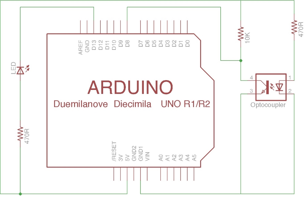
The complete circuit for an optical coin detector
As you can see, from the optocoupler side, I have only added the two resistors I mentioned previously: a 10K to act as a load for the phototransistor and a 470 Ohms one to limit the current through the infrared LED.
There is just an additional consideration. If you take a closer look, you could notice that in this case, I have connected the LED that is going to be used as the output side of our project in a different way than in other examples in the book.
In this ...
Get Arduino Essentials now with the O’Reilly learning platform.
O’Reilly members experience books, live events, courses curated by job role, and more from O’Reilly and nearly 200 top publishers.

