Hardware configuration
Now let's assemble the different components of this project. This is a schematic to help you out:
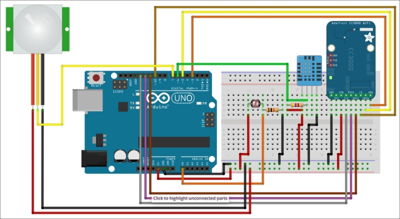
First, connect the power. Connect the Arduino Uno 5V to the red power rail on the breadboard, and the GND pin to the blue power rail. Also, place all the main components on the breadboard.
After that, for the DHT11 sensor, follow the instructions given by the schematic to connect the sensor to the Arduino board. Make sure you don't forget the 4.7k Ohm resistor between the VCC and signal pins.
We are now going to connect the photocell. Start by placing the photocell on the breadboard in series with the 10k Ohm resistor. After that, ...
Get Arduino: Building exciting LED based projects and espionage devices now with the O’Reilly learning platform.
O’Reilly members experience books, live events, courses curated by job role, and more from O’Reilly and nearly 200 top publishers.

