A mini PIR-Arduino alarm
Let's get started. We are going to create a setup in which an LED flashes when motion is detected by the PIR sensor. This is what the setup should look like when connecting the Arduino to the PIR Sensor:
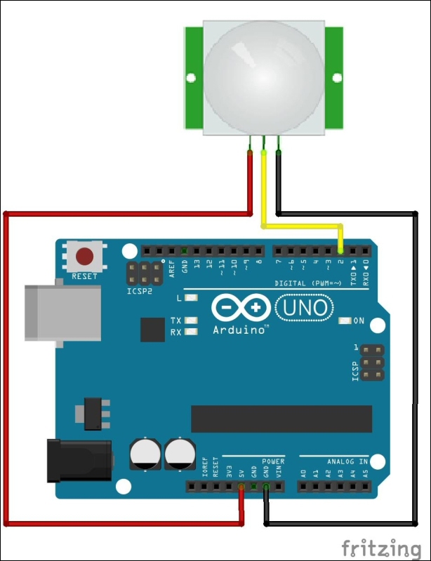
Basically, the connections are as follows:
- GND → GND
- VCC → 5V
- OUT → D02 (digital pin 2)
Note
Digital pins are denoted using D and analog pins are denoted by A. So digital pin 13 is D13 and analog pin 2 is A02.
Open Arduino and load the sketch called PIR_LED.ino, or copy this:
int ledPin = 13; // use the onboard LED int pirPin = 2; // 'out' of PIR connected to digital pin 2 int pirState = LOW; // start the state of the PIR to be ...
Get Arduino: Building exciting LED based projects and espionage devices now with the O’Reilly learning platform.
O’Reilly members experience books, live events, courses curated by job role, and more from O’Reilly and nearly 200 top publishers.

