Pattern recognition
Firstly, go ahead and create this circuit:
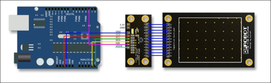
Touch pad circuit (credits: Lauren, DFRobot)
Your capacitive touch pad and its controller (the central component in the image), are connected using the corresponding numbers labeled on the pins. The connections from the Arduino to the controller are as follows (literally the same connections as before):
- GND – GND
- VCC – 5V
- SCL – A5 (analog pin 5)
- SDA – A4
- IQR – D2 (digital pin 2)
- ADDR – no connection necessary
Do not worry if the touch pad doesn't look exactly like this; as long as the connections are fine, everything will work out.
Open up Arduino and go to File | Examples | MPR121 | Examples ...
Get Arduino: Building exciting LED based projects and espionage devices now with the O’Reilly learning platform.
O’Reilly members experience books, live events, courses curated by job role, and more from O’Reilly and nearly 200 top publishers.

