2Problems – Instrumentation
P_2.1 2.4.1.1
Furnace draught systems are typically low pressure, for example 1″ water gauge. The airflow is to be monitored in order to implement air/fuel ratio control. Usually a Venturi is used in order to minimise loss of the available applied draught (see diagram). Your 30 cm diameter air intake ducting has a hood to minimise ingress of foreign material, and proceeds through a Venturi with throat diameter of 15 cm before the forced draught fan.
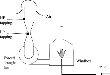
You have calculated a design airflow of 2 th−1 at 25 °C and 101 kPa abs. Estimate the ΔP that will be generated by the Venturi, so that you can specify a suitable DP ...
Get Applied Process Control now with the O’Reilly learning platform.
O’Reilly members experience books, live events, courses curated by job role, and more from O’Reilly and nearly 200 top publishers.

