Appendix F
Transmission Line Theory
At microwave frequencies, the wavelengths have become so small that the physical dimensions of transmission lines and even those of lumped elements, such as resistors, capacitors and inductors, are in the order of these wavelengths. This means that at these frequencies we have to consider effects of waves, such as standing waves and reflections. Depending on the type of transmission line under consideration, these effects may be best characterized by employing a field description or employing a circuit description. In this appendix we will limit ourselves to a circuit description of transmission lines.
The microwave frequency range is somewhat arbitrary, but in practice, frequencies between 300 MHz and 30 GHz may be considered as being in the microwave spectrum.
F.1 Distributed Parameters
A general long (i.e. long with respect to wavelength) two-wire transmission line may be characterized by distributed transmission line parameters, see Figure F.1
Figure F.1 Distributed transmission line parameters in a general long two-wire transmission line.
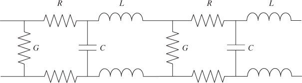
Here R is the sum of resistances in both conductors per unit of length, G is the conductivity per unit of length, L is the self-inductance per unit of length and C is the capacitance per unit of length.
When the distributed transmission line parameters are known, the characteristic impedance, Z0, and ...

