P10.4. Evaluation of the Bias Setup
|
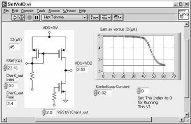
Procedure SetVoID.vi sends out the gate voltage of the driver transistor (M1, NMOS) and then sweeps Chan1_out to set the output bias voltage (Chan1_in) at VDD/2. This VI is a subVI in the gain measurement VI (below, next part). To run this VI as a top VI, set the Index to zero. Set Chan0_out Initial to 0V.
|

Get Analog Electronics with LabVIEW® now with the O’Reilly learning platform.
O’Reilly members experience books, live events, courses curated by job role, and more from O’Reilly and nearly 200 top publishers.

