10 Control Systems and Signal Processing
10.1 Introduction
A control system is often employed to provide a physical system with the ability to meet specified performance goals. In order to design such a system, one usually creates a model of the physical system and a model of the control system so that the combined system can be analyzed and the appropriate control system characteristics chosen. Mathematica provides a collection of commands that allows one to model the system, analyze the system, and plot the characteristics of the system in different ways. In this chapter, we shall demonstrate the usage of several commands that can be employed to design control systems. In addition, we shall illustrate several commands that can be used in various aspects of signal processing and spectral analysis: filters and windows.
10.2 Model Generation: State-Space and Transfer Function Representation
10.2.1 Introduction
Before illustrating the various Mathematica commands that can be used to represent control systems, we shall introduce a permanent magnet motor as a physical system to be modeled and controlled. This system will be used as the specific linear system when many of the commands are introduced. The governing equations for one such system are [1]
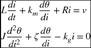
where v = v(t) is the input voltage to the motor windings, i = i(t) is the current in the motor coil, θ = θ(t) is the angular ...
Get An Engineer's Guide to Mathematica now with the O’Reilly learning platform.
O’Reilly members experience books, live events, courses curated by job role, and more from O’Reilly and nearly 200 top publishers.

