7Three‐Phase Transformers
Three‐phase transformers come in many sizes and are found throughout the power system. Many are designed and built for specific applications, like the transmission transformer in Figure 7.1a, while others are ‘off the shelf’ designs, used in many standard distribution applications. The small resin cast transformer shown in Figure 7.1b is an example of such a transformer; it finds application in interior substations where the risk of fire and spillage from oil‐insulated transformers is to be avoided.
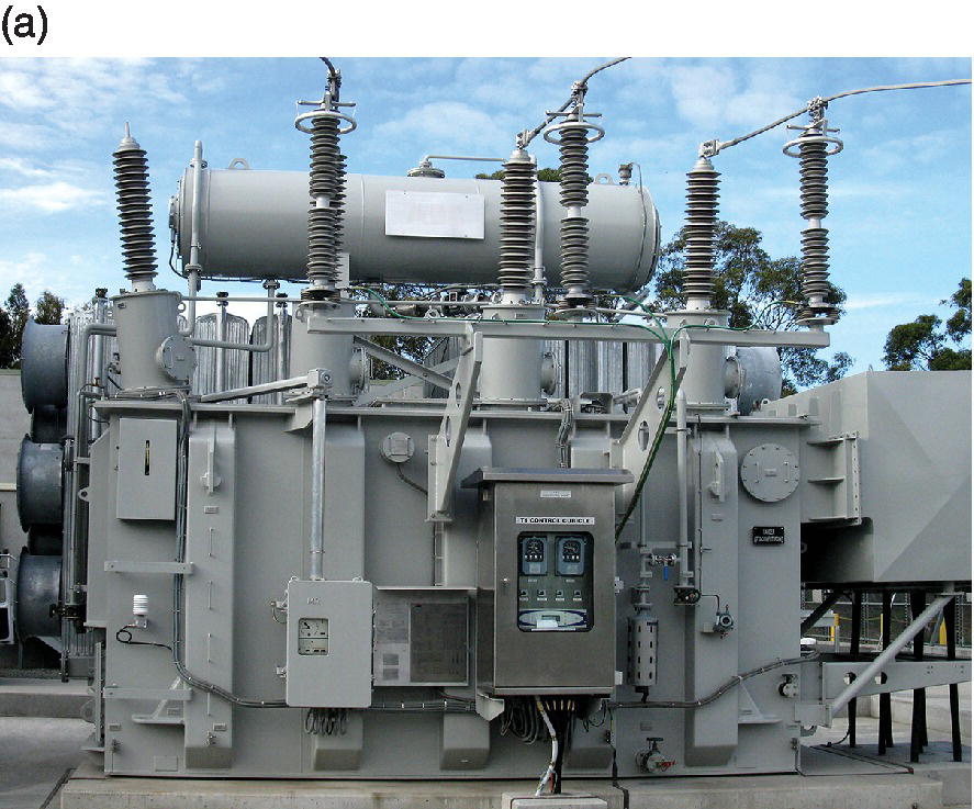
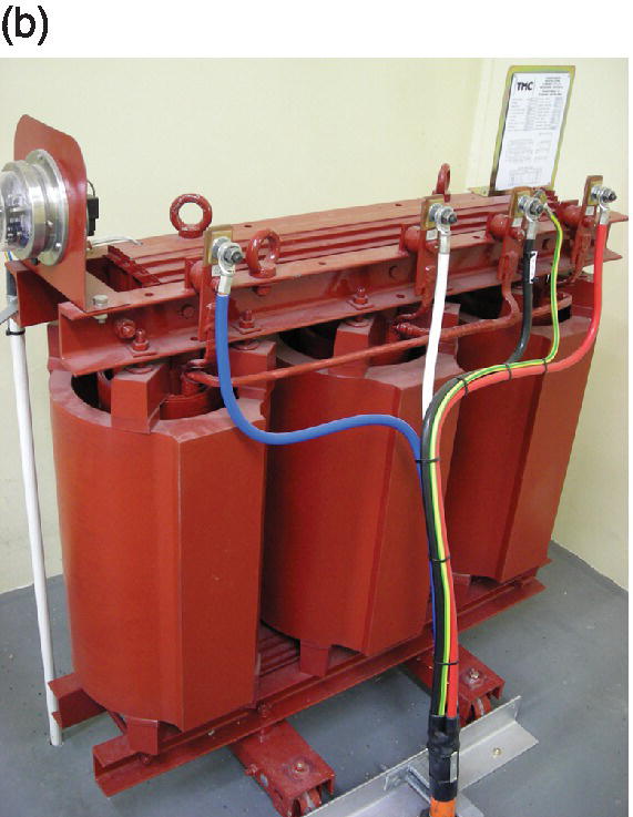
Figure 7.1 (a) 110 kV:33 kV, 60 MVA transformer (b) 22 kV:400 V, 100 kVA transformer.
Three‐phase transformers have essentially the same per‐phase equivalent circuit as do single‐phase transformers, and they present the same impedance to positive and negative sequence currents, since altering the phase sequence of the supply makes no difference to a transformer’s operation. However, the magnetic circuit architecture and the winding arrangements employed can make a large difference to the transformer’s zero‐sequence impedance Z0.
In Chapter 4 we saw that the reactive impedance of a transformer was influenced to a large degree by the presence of an insulation filled duct between the windings, through which the leakage flux from one winding can pass, without ...
Get AC Circuits and Power Systems in Practice now with the O’Reilly learning platform.
O’Reilly members experience books, live events, courses curated by job role, and more from O’Reilly and nearly 200 top publishers.

