Chapter 4. Beamforming in 802.11ac
You can’t depend on your network when your transmission is out of focus.
In wired networking, the biggest innovation of the last two decades was the introduction of Ethernet switching, which dramatically increased network capacity by moving from relatively large collision domains (a multi-port hub) to minimum-sized collision domains (a single port). Wireless LANs have offered great benefits to network users, primarily in the form of mobility, but in return have expanded the collision domain from an Ethernet switch port to the coverage area of an access point. Beamforming and its application in the form of multi-user MIMO in 802.11ac have the potential to change how networks are built and increase capacity well beyond the headline rate of the network equipment. In essence, multi-user MIMO works by taking advantage of beamforming to send frames to spatially diverse locations at the same time, building the first standardized version of an 802.11 “switch.” Beamforming is not inherently more useful in one direction of the link, but typically enterprise access points are less resource-constrained, have access to more memory, power (both computational and electrical), and have more antennas. Therefore, beamforming in the downlink direction from the AP to the client was a ripe area for innovation in the 802.11ac standard.
Beamforming Basics
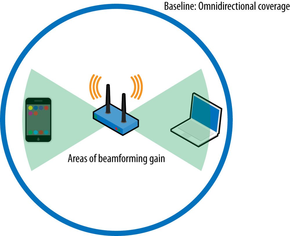
Traditionally, access points have been equipped with omnidirectional antennas, which are so named because they send energy in all directions.[32] Frequently, omnidirectional coverage will be shown as a circle on an overhead-view map, centered on the AP. Omnidirectional antennas are cheap, and more importantly, they spray radio waves in every direction, freeing the AP of the need to track each client. As long as the client is reachable in some direction, the signal from the AP will get there. Of course, the downside to that is that the radio channel is busy in all directions, as shown in Figure 4-1 by the “omnidirectional” circle.
An alternative method of transmission is to focus energy toward a receiver, a process called beamforming.[33] Provided the AP has sufficient information to send the radio energy preferentially in one direction, it is possible to reach farther. The overall effect is illustrated in Figure 4-1. Beamforming focuses energy toward a client, such as to the laptop computer at the right side of the figure. The wedges illustrate the areas where the beamforming focus increases power, and therefore the signal-to-noise ratio and data rates. The mirrored preferential transmission to the left is a common effect of focusing energy in a system with limited antenna elements. However, focusing the energy toward the left and right sides of the figure means that the AP’s range in other directions is smaller.
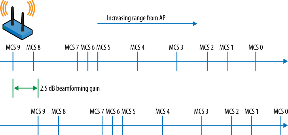
Beamforming increases the performance of wireless networks at medium ranges. At short ranges, the signal power is high enough that the SNR will support the maximum data rate. At long ranges, beamforming does not offer a substantial gain over an omnidirectional antenna, and data rates will be identical to non-beamformed transmissions. Beamforming works by improving what is called the rate over range—at a given distance from the AP, a client device will have better performance. One way to illustrate the improved performance is shown in Figure 4-2. Range from the AP increases to the right, and the distance from the left edge of the figure is meant to roughly approximate the range of that data rate. As described previously, there is a large gap of about 5 dB between the 256-QAM rates and the next set of rates down. The lower line shows the same range data, shifted right to reflect a typical beamforming gain. At any given range, the beamformed data rate will be higher, but it is most effective at pulling in the 64-QAM rates in the middle ranges.
Prior to the development of the 802.11n standard, nearly all access points on the market used antennas with static radiation patterns. APs with internal antennas were almost invariably omnidirectional, while external antennas came in a variety of different radiation patterns. Network designers could choose to use antennas with longer range and narrower beam widths, but once the antenna was selected, its coverage area was set. Beamforming uses antenna arrays to dynamically alter the transmission pattern of the AP, and the transmission pattern can be changed on a per-frame basis. Broadcast and multicast traffic is designed to be received for multiple stations, so a beamforming AP will use traditional omnidirectional transmission methods for broadcast packets to maintain coverage throughout the designed coverage area.
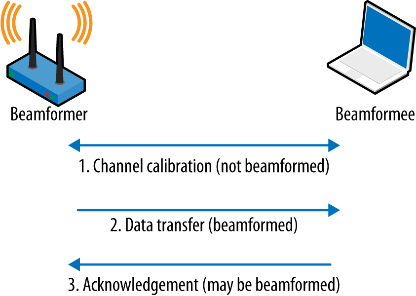
One analogy that I use when describing beamforming is to recall retailer John Wanamaker’s statement that half of his advertising spending was wasted, but he did not know which half of his spending was unproductive. Fortunately for beamforming, it is possible to measure the channel and determine how to best use the available transmit power to reach a client device. Figure 4-3 shows a highly simplified beamforming process consisting of the major steps. In the figure, the AP is sending higher-level data such as IP packets to a laptop as the recipient. The process begins by measuring the radio channel between the two devices in a calibration process. Although in general beamforming may be either explicit or implicit, depending on whether special channel measurement frames are used, in 802.11ac the standard form of beamforming requires the use of channel measurement frames and is only explicit.
Tip
Because 802.11ac beamforming is based on explicit channel measurements, both the transmitter and the receiver must support it.
Any device that shapes its transmitted frames is called a beamformer, and a receiver of such frames is called a beamformee. 802.11 defines new terms for the sender and receiver of beamformed frames because in a single exchange it is possible to have only one initiator and one responder, but a station may be both a beamformer and a beamformee. For example, in Figure 4-3, the AP initiates a frame exchange to the laptop. It begins by exchanging frames to measure the channel. The result of the channel measurement is a derivation of the steering matrix, which is a mathematical description of how to direct transmitted energy toward the receiver. Roughly speaking, it describes how to set up each element of the transmitter’s antenna system to precisely overlap transmissions to reach farther.
After completing the channel measurement, the AP is capable of acting as a beamformer and sending spatially focused frames to the laptop. (Naturally, the process of sending data to the laptop may consist of setting up block acknowledgement operations and multiple aggregate frames.) At the conclusion of the data transmission, the laptop must, as required by 802.11 protocol rules, positively acknowledge receipt of the data. This acknowledgement may be beamformed as well, in which case the laptop will also act as a beamformer for the transmission of acknowledgements. In a frame exchange between two devices, either side may choose to calibrate the channel for beamforming purposes; when client devices have large amounts of data to transmit, the standard allows them to calibrate the channel to steer transmissions toward their serving AP.[34]
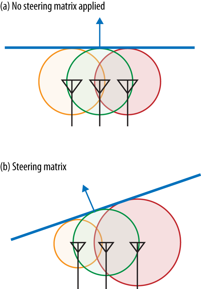
To steer transmissions in a particular direction, a beamformer will subtly alter what is transmitted by each array. As an example, Figure 4-4 shows a simple phase shift. In Figure 4-4(a), all antennas transmit at the same time. As a result, the total transmission radiates in each direction equally. In the figure, this is illustrated by showing that the transmissions from each individual array element go out at the same speed at the same time, and therefore cover the same distance. In Figure 4-4(b), the array applies a phase shift to each element so that the element on the right transmits first and the element on the left transmits last. As a result, the transmissions from the array will converge along a different path that is shifted to the left. The steering matrix is a precise mathematical description of how the antenna array should use each individual element to select a spatial path for the transmission. 802.11ac beamforming is significantly more complicated than is illustrated by this example, however, because beamforming operates on pairwise relationships between the beamformer and the beamformee.
Gains from beamforming are variable and depend on the radio environment, the sophistication of the antenna array on both sides of the link, the relative motion of both sides of the link, and many other factors. Like many features in 802.11ac, beamforming results in a modest improvement in the performance of the underlying protocol, and it must be used with many other techniques to see dramatic performance improvements. A reasonable expectation would be that beamforming can result in a gain of anywhere between 2 to 5 dB, with the best results coming for mid-range transmissions. At short ranges, transmissions are already at the maximum data rate and there will not be any gain in speed. At long ranges, the beamforming gain is not sufficient to add speed.
Tip
Beamforming gains are expected to be approximately 3 dB in the transmitted direction. In practice, this gain will typically be one step up in data rates (increasing one MCS number) for a mid-range transmission.
Null Data Packet (NDP) Beamforming in 802.11ac
One of the biggest changes between 802.11n and 802.11ac is that beamforming has been dramatically simplified. Proprietary beamforming technologies had existed prior to 802.11n, but it was only in 802.11n that a standard for beamforming was introduced. In the 802.11n specification, multiple beamforming methods were described. Before using beamforming, both sides of the link had to agree on one method they shared, but due to the complexity of implementing multiple methods, many product vendors chose not to implement any. To avoid a repeat with 802.11ac, engineers writing the specification settled on just one method of beamforming, called null data packet (NDP) sounding. The second major change in beamforming with 802.11ac has not yet been realized, but it has the potential to dramatically change how much data wireless networks can support. 802.11ac’s second wave of products will introduce multi-user MIMO, an application of MIMO techniques that allows simultaneous transmission to multiple clients.
Channel measurement (sounding) procedures
Beamforming depends on channel calibration procedures, called channel sounding in the 802.11ac standard, to determine how to radiate energy in a preferred direction. Many factors may influence how to steer a beam in a particular direction. Within the multi-carrier OFDM channel used by 802.11ac, there may be a strong frequency-dependent response that requires limiting data rates over the channel. Alternatively, between two 802.11ac devices, a particular frequency may respond much more strongly to one path than another. Beamforming enables the endpoints at either side of a link to get maximum performance by taking advantage of channels that have strong performance while avoiding paths and carriers that have weak performance.[36] Mathematically, the ability to steer energy is represented by the steering matrix, which is given the letter Q in 802.11ac. Matrices are used to represent steering information because they are an excellent tool for representing the frequency response from each transmission chain in the array over each transmission stream. Matrix operations allow the spatial mapper to alter the signal to be transmitted for each OFDM subcarrier over each path to the receiver in one operation. Naturally, after applying the steering matrix to the data for transmission, it will leave the antenna array in a decidedly non-omnidirectional pattern.
Channel sounding consists of three major steps:
The beamformer begins the process by transmitting a Null Data Packet Announcement frame, which is used to gain control of the channel and identify beamformees. Beamformees will respond to the NDP Announcement, while all other stations will simply defer channel access until the sounding sequence is complete.
The beamformer follows the NDP Announcement with a null data packet. The value of an NDP is that the receiver can analyze the OFDM training fields to calculate the channel response, and therefore the steering matrix. For multi-user transmissions, multiple NDPs may be transmitted.
The beamformee analyzes the training fields in the received NDP and calculates a feedback matrix. The feedback matrix, referred to by the letter V in the 802.11ac specification, enables the beamformer to calculate the steering matrix.
The beamformer receives the feedback matrix and calculates the steering matrix to direct transmissions toward the beamformee.
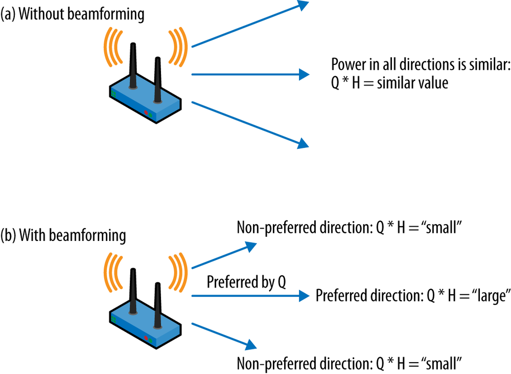
With the steering matrix in hand, the beamformer can then transmit frames biased in a particular direction, as shown in Figure 4-5. Without beamforming, energy is radiated in all directions more or less equally. Along any direction away from the beamformer, the signal level will be roughly comparable (assuming an ideal omnidirectional antenna). If the transmitter applies a steering matrix, however, the array will send energy in a way that prefers one path. On the preferred path, transmissions from the array will reinforce each other and become stronger, and on other paths, the transmissions from the array will interfere with each other and become weaker. In effect, the combination of the steering matrix and the channel determines whether a signal becomes stronger or weaker.
Channel sounding procedures do have a cost in airtime because the sounding exchange must complete before a beamformed transmission can be sent. If the speed gain from transmitting a beamformed frame is not sufficient to offset the airtime consumed by the sounding exchange, the overall speed will be slower. Roughly speaking, a sounding exchange requires 500 microseconds.[37] Once the effect of contention is added into the mix, a rough guideline is that the sounding procedure requires about 0.5% to 1% of available airtime, which can add up to a substantial fraction of available capacity on networks with high numbers of clients.
The feedback matrix
The key to beamforming is calculating the steering matrix Q for the channel between the beamformer and the beamformee. The steering matrix can potentially have quite large dimensions because it represents the channel behavior between each of the transmitters in the beamformer’s array and each of the receivers in the beamformee’s array. Rather than transmitting a steering matrix, the beamformee calculates a feedback matrix and compresses it so that it can be represented by a smaller frame and thus take up less airtime. Compression of the beamforming matrix is accomplished by using matrix operations to send a representative set of values that can be used to reconstitute the matrix instead of sending the raw matrix itself.
To calculate the feedback matrix, the beamformee runs through the following procedure:[38]
Calculating the feedback matrix can only begin after receiving the NDP from the beamformer. Once the NDP is received, each OFDM subcarrier is processed independently in its own matrix that describes the performance of the subcarrier between each transmitter antenna element and each receiver antenna element. The contents of the matrix are based on the received power and phase shifts between each pair of antennas.
The feedback matrix is transformed by a matrix multiplication operation called a Givens rotation, which depends on parameters called “angles.” Rather than transmitting the full feedback matrix, the beamformee calculates the angles based on the matrix rotation. The 802.11ac standard specifies the order in which these angles are transmitted so that the beamformer can receive a long string of bits and appropriately delimit each angle.
Having calculated the angles, the beamformee assembles them into the compressed feedback form and returns them to the beamformer. Only one set of angles is required to summarize the radio link performance for all of the OFDM subcarriers, though naturally, the set of angles can be quite large with wider channels.
The beamformer receives the feedback matrix and uses it to calculate the steering matrix for transmissions to the beamformee.
One feedback matrix is sent by each beamformee. In single-user beamforming, there is one feedback matrix from the beamformee and one steering matrix used. In multi-user beamforming, each beamformee sends a feedback matrix and the beamformer must maintain a steering matrix for each client.
When transmitting the feedback matrix, there are three main factors that determine its size. First, wider channels have more OFDM subcarriers, so the feedback matrix must be larger to accommodate them. Second, the higher the number of pairwise combinations of transmitter and receiver antennas is, the larger the matrix will be. Finally, 802.11ac allows two different representations of the angle values to enable devices to use higher resolution when necessary. The relevant sizes are summarized in Table 4-1. Multi-user MIMO requires higher resolution because of the need to avoid inter-user interference, a problem unique to multi-user transmissions.
| Number of subcarriers[a] | Per-subcarrier angle count[b] | Angle field size |
| 20 MHz channel: 52 subcarriers | 2x2: 2 angles/subcarrier | Single-user: 6 bits or 10 bits/angle |
| 40 MHz channel: 108 subcarriers | 3x3: 6 angles/subcarrier | Multi-user: 12 bits or 16 bits/angle |
| 80 MHz channel: 234 subcarriers | 4x4: 12 angles/subcarrier | |
| 160 MHz channel: 486 subcarriers | 6x6: 30 angles/subcarrier | |
| 8x8: 56 angles/subcarrier | ||
[a] Subcarriers can be grouped to reduce the report size. [b] Many combinations of size for the beamforming matrix are available. This table shows the maximum number of angles because it focuses on symmetric systems, but combinations are available for any number of transmitters from 2 through 8, and any number of receivers up to the number of transmitters. | ||
To estimate the size of the feedback matrix, multiply the results of each of the three columns in Table 4-1:
- Single-user 2x2 MIMO @ 20 MHz, low resolution: 78-byte report
52 subcarriers x 2 angles/subcarrier x 6 bits/angle = 624 bits or 78 bytes. This is the smallest steering matrix available in 802.11ac.
- Single-user 3x3 MIMO @ 80 MHz, high resolution: 1.7 kB report
234 subcarriers x 6 angles/subcarrier x 10 bits/angle = 14,040 bits or 1.7 kB. This will be a typical steering matrix for a single-user MIMO system released in the first wave of 802.11ac.
- Single-user 4x4 MIMO @ 80 MHz, high resolution: 3.4 kB report
This is the same as the previous example, but it adds an additional transmitter and receiver. In a 4x4 system there are more degrees of freedom, which is why there are more angles required per subcarrier.
- Multi-user 8x8 MIMO @ 80 MHz, high resolution: 53 kB report
486 subcarriers x 56 angles/subcarrier x 16 bits/angle = 435,456 bits or 53 kB. Large sets of angles can group subcarriers together in order to reduce the report size and help it fit into a frame. In practice, a multi-user report with 80 MHz channels would group subcarriers to reduce the report size.
Single-User (SU) Beamforming
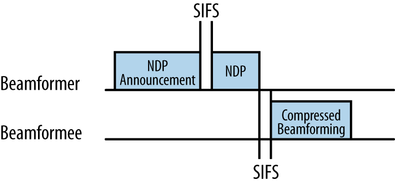
Single-user beamforming is readily understandable because its purpose is to shape a transmission from a single transmitter to a single receiver. As shown in Figure 4-6, the beamformer sends a null data packet, which is a frame with a known fixed format. By analyzing the received NDP frame, the beamformee calculates a feedback matrix that is sent in a reply frame. Beamformees do not send a steering matrix directly because the beamforming sounding protocol needs to enable multiple-user MIMO, as described in the next section.
Channel Calibration for Single-User Beamforming
The channel calibration procedure is carried out as a single operation, in which the beamformer and beamformee cooperatively measure the channel to provide the raw data needed to calculate the steering matrix. The sounding procedure does not transmit the steering matrix directly, but instead works to exchange all the information necessary for the beamformer to calculate its own steering matrix.
NDP Announcement frame
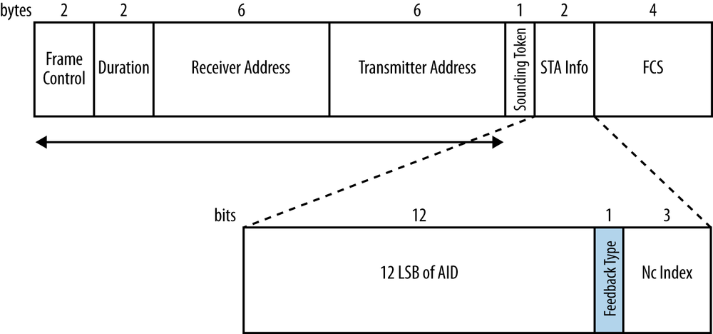
The channel sounding process begins when the beamformer transmits a Null Data Packet Announcement frame, which is a control frame and is depicted in Figure 4-7. The entire channel sounding process is carried out in one burst, so the duration set in an NDP Announcement corresponds to the length of the full exchange of three frames. In single-user MIMO beamforming, the NDP Announcement frame relays the size of the feedback matrix by identifying the number of columns in the feedback matrix.
The main purpose of the NDP Announcement frame is to carry a single STA Info field for the intended beamformee. The STA Info field is two bytes long and consists of three fields:
- AID12 (12 least significant bits of the intended beamformee’s association ID)
Upon association to an 802.11 access point, client devices are assigned an association ID. The least significant 12 bits of the beamformee’s association ID are included in this field. When a client device acts as a beamformer, this field is set to 0 because the AP does not have an association ID.
- Feedback Type
In a single-user NDP Announcement frame, this field is always 0.
- Nc Index
This index describes the number of columns in the feedback matrix, with one column for each spatial stream. As a three-bit field it can take on eight values, which matches the eight streams supported by 802.11ac. This field is set to the number of spatial streams minus one.
NDP frame
Upon transmission of the NDP Announcement frame, the beamformer next transmits a Null Data Packet frame, which is shown in Figure 4-8. The reason for the name “null data packet” should be obvious in looking at the frame; Figure 4-8 shows a PLCP frame with no data field, so there is no 802.11 MAC frame. Channel sounding can be carried out by analyzing the received training symbols in the PLCP header, so no MAC data is required in an NDP. Within an NDP there is one VHT Long Training Field (VHT-LTF) for each spatial stream used in transmission, and hence in the beamformed data transmission.

VHT Compressed Beamforming Action frame
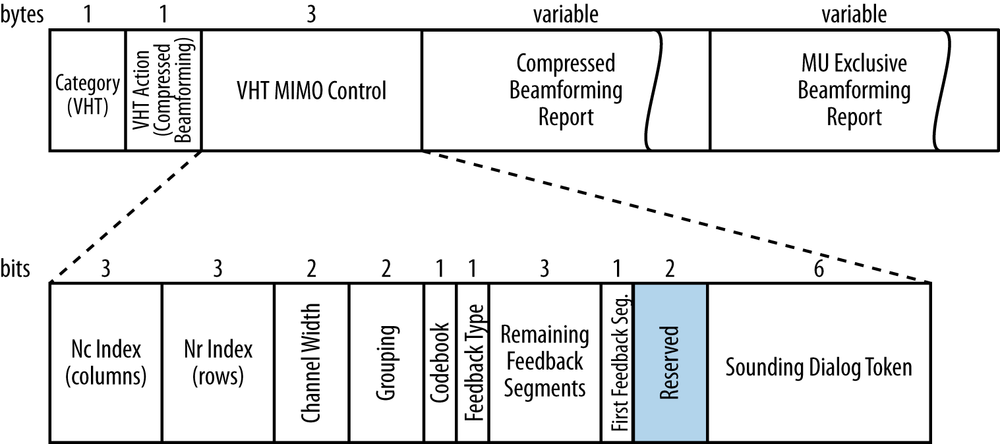
Following receipt of the NDP, the beamformee responds with a feedback matrix. The feedback matrix tells the beamformer how the training symbols in the NDP were received, and therefore how the beamformer should steer the frame to the beamformee. Figure 4-9 shows the format of the compressed beamforming report frame used in single-user MIMO. The Action frame header indicates that the frame contains a feedback matrix.
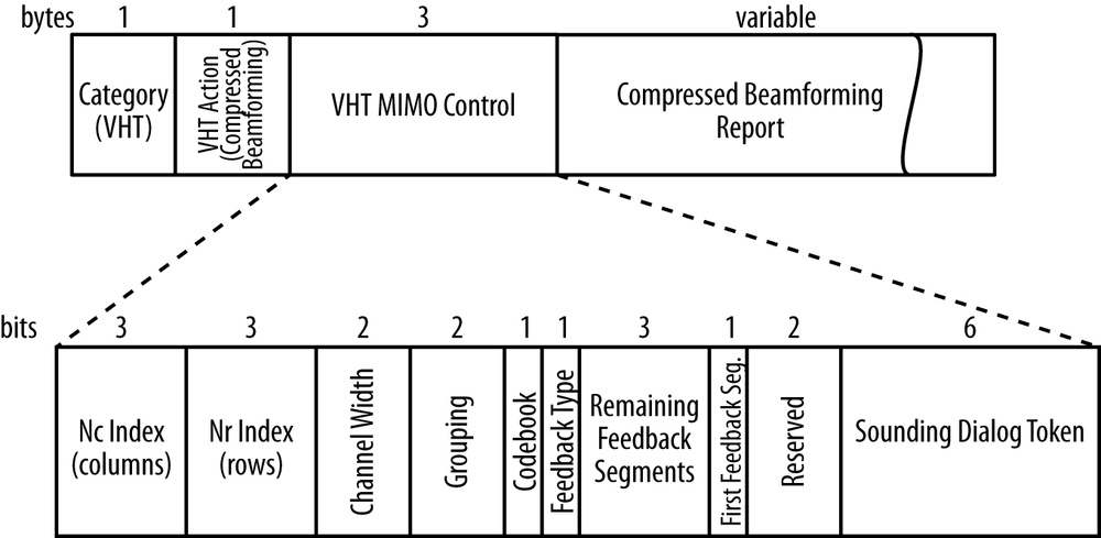
The VHT MIMO Control field, included next, enables a beamformer to interpret the feedback matrix by describing the following attributes:
- Size of the feedback matrix (6 bits)
The Nc Index and Nr Index fields describe the size of the feedback matrix in terms of the number of columns and the number of rows. When using beamformed transmissions over large numbers of spatial streams, the matrix will be quite large.
- Channel width (2 bits)
The feedback matrix’s size also depends on the size of the underlying channel. Wider channels require larger feedback matrices because there are more individual carriers to measure.
- Grouping (2 bits)
When parts of the beamforming matrix are repeated, the beamformee can group multiple spatial streams together to reduce the size of the transmitted matrix.
- Codebook (1 bit)
Roughly speaking, a beamforming matrix is used to describe the phase shifts required by each antenna element (see Figure 4-4). 802.11ac transmits the information on these angles as a long string of bits; the receiver of a steering matrix needs to know where to split the bit field into individual matrix elements, and this field is used to describe the representation of the data.
- Type of feedback (1 bit)
Obviously, in single-user MIMO, the feedback type will be single user.
- Flow control (10 bits)
The Remaining Feedback Segments and First Feedback Segment fields are used together with the Sounding Dialog Token to match the response from the beamformee to the beamformer’s request. In very large matrices with wide bandwidths and high numbers of spatial streams, the matrix will be quite large and therefore may need to be sent to the beamformer in multiple steps.
Multi-User (MU) Beamforming
By simplifying beamforming to use one method of channel sounding, 802.11ac will enable wider use of standards-based beamforming. More significant, however, is the inclusion of multi-user (MU) MIMO beamforming in 802.11ac. Prior to the introduction of multi-user beamforming, all 802.11 devices could send a transmission to only one device at a time. Just as Ethernet switches reduced the scope for collisions from a large network down to a single port, multi-user MIMO reduces the spatial collision domain. By using MU-MIMO, an AP may transmit to multiple receiving stations simultaneously.
Tip
Due to the need for sophisticated antenna systems and signal processing, MU-MIMO in 802.11ac can be used only in the downstream direction, from an AP to multiple client devices.
One important capability that MU-MIMO brings to 802.11ac is its support of single-stream devices. Prior to 802.11ac, beamforming worked to increase the signal-to-noise ratio of a link to a single device, but the devices on the network often limited its benefits. Many small battery-powered devices are capable of only a single spatial stream, and thus receive only limited benefits from single-user MIMO. With 802.11ac’s multi-user MIMO, a single transmission time can be used to send frames to multiple single-stream receivers. The 802.11ac standard allows up to four different receiver groups within one MU-MIMO transmission.
Tip
Multi-user MIMO can transmit simultaneously to multiple single-stream devices, which enables the network to more efficiently serve increasingly common battery-powered devices such as phones and tablets.
Channel Calibration for Multi-User Beamforming
To support multi-user MIMO beamforming, 802.11ac uses an extended version of the channel sounding exchange. As shown in Figure 4-10, the multi-user channel sounding procedure requires a response from all beamformees. Each beamformee contributes information in a feedback matrix, and the beamformer uses multiple feedback matrices to produce one steering matrix.
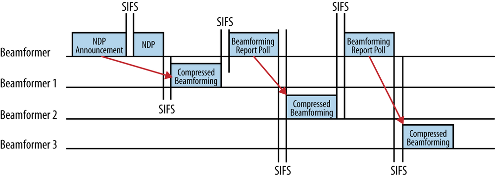
In Figure 4-10, the sounding procedure starts off exactly as it did in the single-user case, with an NDP Announcement and NDP that put the transmission out to begin the calibration. However, to retrieve the feedback matrix from each beamformee, the multi-user sounding procedure needs a new frame, the Beamforming Report Poll frame, to ensure that responses from all beamformees are collected. Figure 4-10 shows three beamformees, and therefore the beamformer must use two poll frames to obtain the feedback matrices from the second and third beamformees. (No poll frame is required for the first station named in the NDP Announcement frame, but the second and subsequent beamformees must be polled.) After receiving multiple responses, the beamformer will integrate all the responses together into a master steering matrix.
NDP Announcement frame
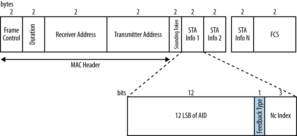
As in the single-user case, the channel sounding procedure is started by transmission of an NDP Announcement frame. The format of the NDP Announcement frame in the multi-user case is similar to the single-user NDP Announcement, with one important change. As shown in Figure 4-11, a multi-user NDP Announcement frame includes multiple Station Information records, one for each beamformee. In the Station Information fields, the NDP Announcement frame is used to request multi-user feedback as well. When an NDP Announcement is sent to multiple receivers, as it is when starting the MU-MIMO sounding process, the receiver address is the broadcast address.
NDP frame
Upon transmission of the NDP Announcement frame, the beamformer next transmits a Null Data Packet frame. Like NDP Announcements, null data packets are sent in single-user mode. Therefore, even in multi-user MIMO sounding, the format will be identical to the single-user format shown in Figure 4-8. A single null data packet has no MAC header information and will be received by all devices. Each device can use the received training frames in the null data packet to calculate its feedback matrix.
Compressed Beamforming Action frame
The Compressed Beamforming Action frame serves the same purpose in multi-user MIMO as it does in single-user MIMO. However, the multi-user format of the frame includes an extra field, the Multi-User Exclusive Beamforming Report field, at the end of the frame. This field carries signal-to-noise ratio differences between subcarriers and is needed to update the steering matrix when there are multiple recipients. Both report fields shown in Figure 4-12 are indicated as variable because their size depends on the number of spatial streams as well as the channel bandwidth.
Beamforming Report Poll frame
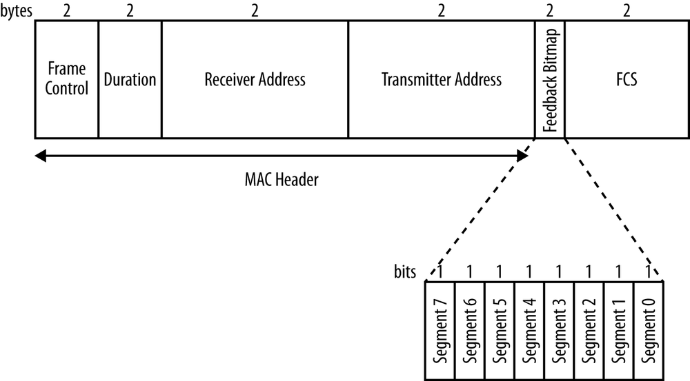
To retrieve additional feedback from the second and subsequent beamformees, the beamformer must use the Beamforming Report Poll frame, which is a control frame. This frame is quite simple, as can be seen in Figure 4-13: it is essentially a one-byte field of retransmission requests. Each bit in the Feedback Bitmap field requests one feedback segment to be retransmitted.
Multi-User MIMO Transmission
Once the multi-user channel sounding is complete, an AP can proceed to send a multi-user transmission. Each beamformee in a multi-user transmission is called, not surprisingly, a user. 802.11ac supports sending up to four multi-user MIMO transmissions at one time, and the 802.11ac MAC protocol includes ways to negotiate the capabilities of each of the simultaneous transmissions. Each multi-user MIMO transmission may have a different number of spatial streams and may have its own modulation speed and coding.
Tip
MU-MIMO transmissions are limited to four clients.
The complexity of multi-user MIMO transmission is illustrated in Figure 4-14. Just as with single-user MIMO, there are potentially multiple paths between each of the AP’s antenna elements and the each of the users’ antenna elements. However, there is an additional complexity to multi-user MIMO in that the number of potential paths that need to be represented in the steering matrix includes every path between each of the AP’s antenna elements and every user antenna element. Each user transmission must be separately modulated.
To limit the system complexity, each user in an 802.11ac MU-MIMO setup is restricted to four spatial streams. 802.11ac actually supports up to eight spatial streams in the standard (though it may be some time after the initial release of 802.11ac in 2013 before hardware that implements more than four spatial streams is available). One of the trade-offs in a multi-user system is that the throughput for an individual device is lower because it can only support four streams.
Tip
MU-MIMO clients are limited to four spatial streams. If you want to go faster, you’ll have to use single-user MIMO transmissions.
PHY changes for MU-MIMO
To transmit to multiple streams, a few small changes are made to the PLCP. The fields remain very similar to the descriptions in PHY-Level Framing, but there are a few important changes. Figure 4-15 shows the VHT Signal A field for multi-user transmissions (compare it to Figure 2-7 for the single-user format).
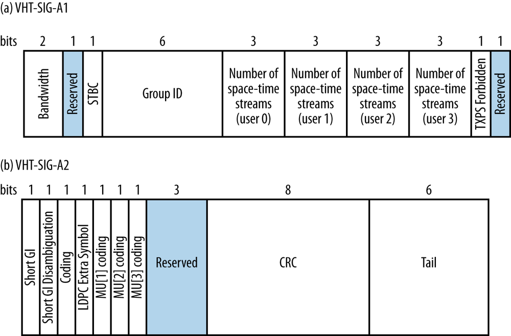
The changes from the single-user version of the VHT Signal A field are:
- Group ID (6 bits)
The Group ID is a protocol-layer abstraction that enables the receiver of a multi-user transmission to determine if the payload of the PLCP includes a frame sent to the receiver.
- Number of space-time streams for users 0 to 3 (12 bits, 3 for each user)
A multi-user transmission may be sent to up to four simultaneous users. These sub-fields tell the recipients how many space-time streams are used for their transmissions.
- Multi-user coding for users 1 to 3 (3 bits)
Where the single-user version of the VHT Signal A field holds the MCS for the payload of the PLCP, the multi-user version has bits that indicate whether convolutional coding or LDPC is used. The MCS values for each of the user streams are moved to the VHT Signal B field.
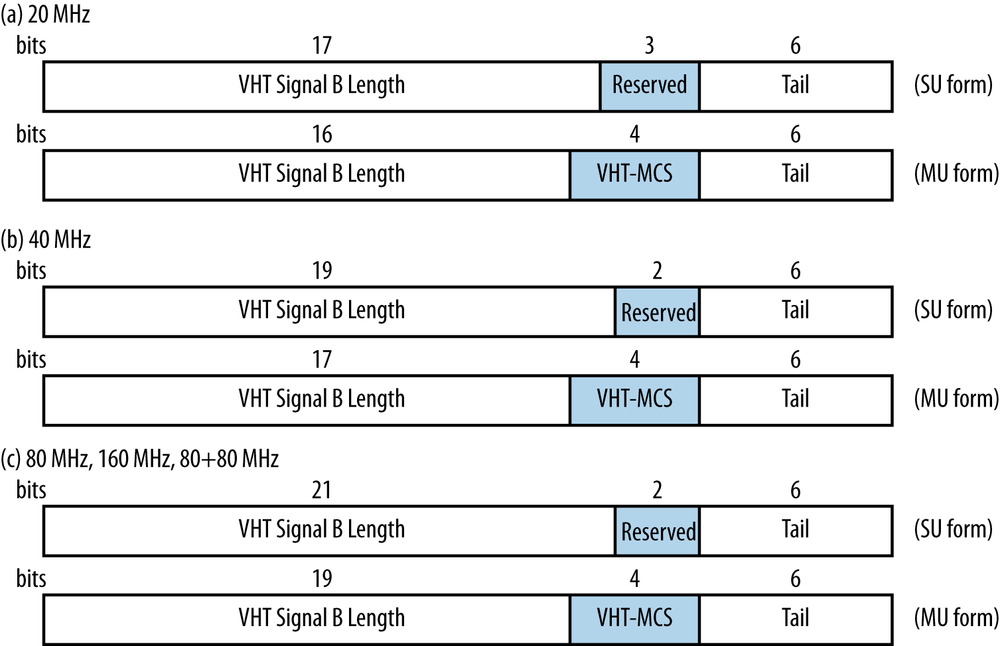
In the PLCP header, there is an OFDM-modulated header and a VHT-modulated header. In a multi-user transmission, the VHT-modulated PLCP header is available on a per-user basis, and each user has its own VHT Signal B. Figure 4-16 compares the multi-user format to the single-user format described in Chapter 2. Because the VHT Signal B field is available on a per-user basis, it includes the MCS value for the data rate. Due to the smaller number of spatial streams available to multi-user transmissions, the total number of bits devoted to the length of the individual user frames can be smaller without negative effect.
Transmission and reception of multi-user data streams
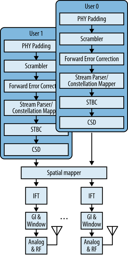
When transmitting a multi-user MIMO frame set, 802.11ac handles each individual user separately up to the point at which signals are combined for the analog frontend in the spatial mapper. Figure 4-17 shows a highly simplified block diagram of a two-user MIMO transmission system. Each user’s input is treated independently in the digital system, where it is padded and scrambled and has forward error correction applied. Individual transmissions in a multi-user MIMO system can be coded independently, so one user may have convolutional coding and a second user may use LDPC. Each transmission is modulated at its own rate, and may or may not have STBC applied. Multiple user transmissions are only combined together in the spatial mapper, at which point the steering matrix derived from the sounding process is applied to the collective data of all users.
The most important task for a receiver of a multi-user transmission is to determine how to get at its own transmission within the multi-user stream of data while ignoring all the others. When decoding the transmissions, a receiver can process not only its own stream’s VHT-modulated training fields, but also the other streams in the transmission. For obvious reasons, the other streams are called interfering streams. 802.11ac places no requirement on a station to decode the interfering data streams, but doing so will reduce the effects of interference.
MU-MIMO Implementation
Although it may seem like a relatively straightforward application of the MIMO technology that has been successfully applied in 802.11n for the better part of a decade, building a multi-user MIMO product has significant complexity over and above building a single-user MIMO product. One of the major limitations on MU-MIMO speeds is inter-user interference, which is caused by beamformees that are “too close” to each other, such that the transmission to one beamformee interferes with the transmission to another beamformee. Mitigating inter-user interference is a major hurdle for practical applications of MU-MIMO. Multi-user beamformers will likely measure the channel significantly more often to maintain up-to-date spatial location information (see the sidebar Heisenberg Beamforming: Single-User and Multi-User Beamforming Compared). Finally, MU-MIMO has significant effects on the queuing system in an access point. High-priority frames are still transmitted quickly, but MU-MIMO enables low-priority frames to secondary clients to be pulled forward in time.
Null steering
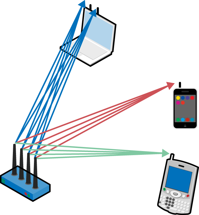
Inter-user interference occurs because two receivers of multi-user transmissions are not sufficiently separated. The primary goal in sending a multi-user transmission is to avoid causing this interference. Figure 4-18 illustrates the primary approach, sometimes called null steering. Beamforming focuses energy at a receiver, and a byproduct of this focusing effect is that outside of the intended reception area, the received signal is weaker. Multi-user MIMO transmissions combine both techniques. In the figure, there are three simultaneous transmissions. The AP has computed a steering matrix Q for each of them based on the channel measurements; the matrix H describes the effect of the channel on the transmission. In an ideal scenario, the steering matrix for each client would produce a high signal for the intended transmission, and a “null” (no reception) for the other two transmissions in the multi-user set. For example, the steering matrix for the blue client at the top of the figure would produce the frame transmitted to the blue station, but would also cancel out the transmissions to the red and green clients.

Mathematically, effective null steering requires as many degrees of freedom as possible in the matrix. When translated into the physical world of building products, the extra degrees of freedom in the matrix are represented by additional antennas in the array. By increasing the number of antenna elements, it is possible to more accurately direct transmissions in a preferred direction and, just as importantly, ensure that the transmission is sent only in the preferred direction.
Acknowledgement in MU-MIMO
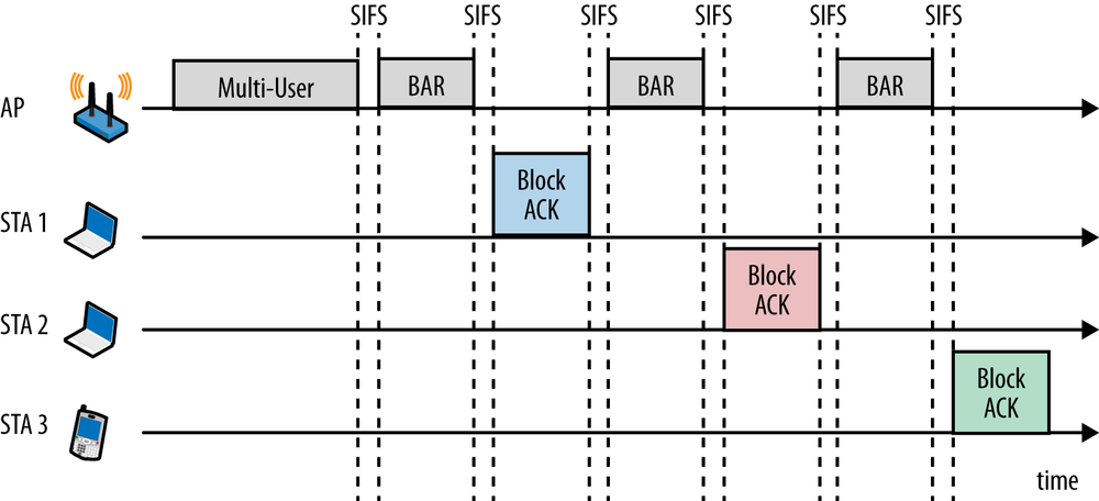
Multi-user MIMO in 802.11ac works only in the downlink direction from the AP to clients. A multi-user frame can be transmitted to multiple receivers at the same time, but the acknowledgements must be transmitted individually in the uplink direction. Every frame transmitted in 802.11ac is an aggregate frame, so 802.11ac uses the block acknowledgement procedure originally defined in 802.11n. Figure 4-19 shows one potential acknowledgement sequence for the frames transmitted by the system described in the previous section. After gaining control of the channel, the AP will transmit a multi-user frame to all receivers. In block acknowledgement, the transmitter retains control of the channel and individually requests acknowledgements where required. In the figure, the AP follows its data transmission with explicit block acknowledgement requests to each of the three receivers.
Queuing and quality of service
Multi-user MIMO systems retain the same four queues for voice, video, best effort, and background traffic originally developed as part of the 802.11 quality of service architecture. Queuing becomes significantly more complicated with MU-MIMO, though, because a single multi-user transmission may mix high-priority frames to a priority receiver with lower-priority frames sent to a spatially distinct receiver. For example, a multi-user transmission may be scheduled to transmit voice frames to a single-stream phone and then use that transmission time to also send lower-priority data to other devices at the same time.
When an AP gains control of the channel for transmission of a multi-user transmission, it is doing so for the purpose of transmitting frames to one user. In Figure 4-14, for example, an AP may gain control of the channel in order to transmit voice frames to the phone and then choose other waiting frames for the two laptops. The access category of the traffic that drives the AP to gain control of the channel is called the primary access category (AC), while other access categories are called secondary access categories. Secondary ACs are used to support additional stations.
Figure 4-20 shows a simple example of the additional queuing required. Frames are queued from the higher protocol layers at the top of the figure, and the AP maintains four access categories for frames. In a single-user system, it is likely that frames would be transmitted from high-priority queues first, followed by lower-priority queues. In multi-user MIMO, however, frames from lower priority queues may “piggyback” onto channel access.
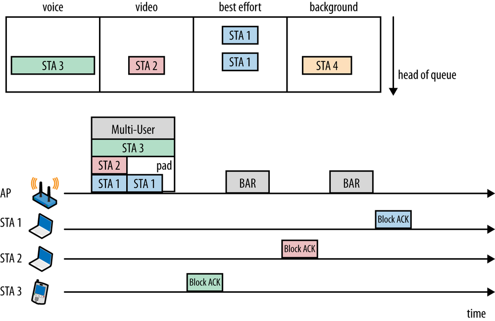
In this figure, there is a relatively long frame at the head of the voice queue destined for the phone. When the AP gains control of the channel to transmit the voice frame to the phone, the voice access category becomes the primary AC. The AP begins constructing a multi-user frame, and can now consider other frames and other access categories for transmission.
Frames for secondary ACs can be added into a multi-user transmission so long as they do not lengthen the overall frame. For instance, within the transmit queues in the AP it is possible to select a video frame for one laptop and two best-effort data frames for the other laptop while retaining the same overall frame transmission time, provided that the two laptop devices are located in directions that are not subject to causing inter-user interference. Even if there are other frames available, such as the background frame shown to the fourth station in Figure 4-20, they may not be included in a multi-user transmission if the receiver is not spatially distinct.
Frames on the secondary ACs gain access to the medium more quickly than they would in single-user transmission, but only because they are riding on the coattails of the frame in the primary access category. In effect, with multi-user transmission it is possible for a low-priority frame to jump the queue, provided that the low-priority frame can be transmitted simultaneously with a higher-priority non-interfering frame.
802.11ac does not specify many constraints on the design of the queuing system in an AP. Secondary ACs cannot increase the amount of airtime consumed by a multi-user packet, but given that one rule, it is possible to optimize a queuing system around many other attributes. It is acceptable to pick frames on the secondary AC that can be transmitted at the highest data rates to maximize overall throughput. Alternatively, a queuing system could be designed to transmit to the maximum number of non-overlapping receivers on secondary ACs.
[32] Omni antenna coverage is not a perfect sphere. It’s usually more like a doughnut with an AP at the center and the torus spread out horizontally. Most AP coverage diagrams are drawn from the perspective of an observer looking down on the network from the top, though, so omnidirectional antennas are depicted as a having a circular coverage area.
[33] Beamforming is sometimes also called beam steering, for obvious reasons. I prefer beam steering as a term because it describes the effects of the process better, but I have chosen to use the term preferred by the authors of the standard in this book.
[34] In practice, beamforming is easier to do in the “downstream” (AP to client) direction because APs have more sophisticated antenna arrays.
[35] For more information, see my blog post at http://blogs.aerohive.com/blog/the-wi-fi-security-blog/did-the-fcc-really-limit-80211ac-beamforming.
[36] One subtle distinction between 802.11n and 802.11ac is that the latter does away with the unequal modulation (UEQM) modes. UEQM was originally standardized because one effect of beamforming may be to emphasize that certain carriers or paths are less able to sustain high data rates, due to frequency-specific effects. One of the reasons why UEQM was never widely deployed with 802.11n is that very few 802.11n implementations ever made use of explicit beamforming.
[37] Timing for a sounding exchange is determined mainly by the size of the feedback matrix. Both the NDP Announcement and the NDP are fairly short. After gaining control of the channel, the NDPA and NDP frames require about 100 microseconds. For computing the duration required for the feedback matrix, it’s necessary to make an assumption about the achievable data rate, which is itself a function of the channel bandwidth and modulation and coding. To get to a rough figure of 500 microseconds, I assumed that the channel was able to support a data rate at the lower end of the middle range of data rates.
[38] Feedback matrix calculations are not for the faint of heart. 802.11ac borrows heavily from the beamforming procedures first established in 802.11n. If you want the gory details of the matrix math used to calculate the feedback matrix, see clause 20.3.12.3 in 802.11-2012, and read up on Givens rotations, which are named after the scientist at the Argonne National Laboratory who invented them.
Get 802.11ac: A Survival Guide now with the O’Reilly learning platform.
O’Reilly members experience books, live events, courses curated by job role, and more from O’Reilly and nearly 200 top publishers.

