Chapter 4. Hacking the Outdoors
Electronics outside, you say? Isn’t that a bad idea? We do have a couple of water-resistant suggestions ([Hack #39] and [Hack #40]). But we also have ideas for how to put your Pi to use on your outdoor projects, from monitoring your garden ([Hack #38]) to controlling your holiday lights ([Hack #45]).
Hack 37. Tell the Temperature Outside (Without Going Out There)
The outside temperature is not a constant value; it fluctuates, and we know you like to know what it is. Whether you’re helping plants stay healthy or just want to know how many layers of clothes to wear, this hack can help!
[Hack #5] shows that the Raspberry Pi measures the temperature of its BCM2835 system-on-chip, but this is different. In order to read the temperature near the Raspberry Pi (or even nowhere near it), you’ll need to connect a temperature sensor. While Linux supports some USB thermometers, it is just as simple (and arguably more fun), to wire up a simple temperature sensor to the GPIO on the Raspberry Pi.
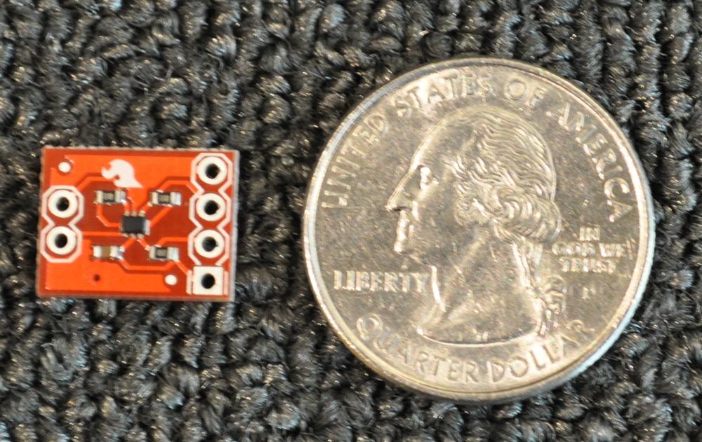
This hack uses the Texas Instruments TMP102 I2C temperature sensor for the following reasons:
- It is very small. Smaller than a quarter. See Figure 4-1 for proof.
- It is a digital sensor (this makes the wiring much easier and the results much more accurate).
- Sparkfun sells it already connected to a breakout board.
- It is cheap (less than $6 USD at the time of this writing).
- It is accurate over a range of temperatures from -25°C and +85°C. (That’s -13° to 185°F.)
Depending on which Linux distribution you are using, you might not have all the drivers necessary to use the TMP102. Both Raspbian and Pidora are missing the driver for the TMP102. You can enable the support for this driver if you build a custom kernel from source, as covered in [Hack #22]. Be sure that you have enabled (compiled in) CONFIG_I2C, CONFIG_I2C_CHARDEV, and CONFIG_I2C_BCM2708.
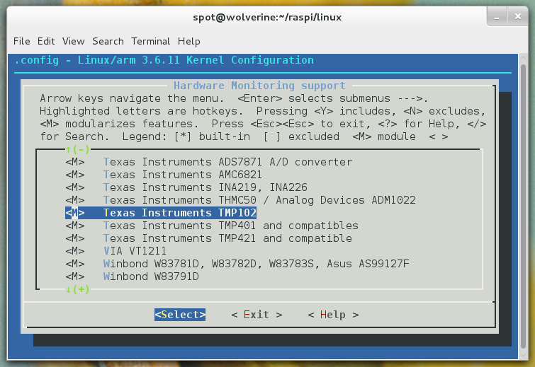
Because you will be using the lm_sensors userspace component to get readings from the TMP102, you will need to be sure to enable “Hardware Monitoring support” (CONFIG_HWMON) under Device Drivers. You also need to have CONFIG_SENSORS_TMP102 enabled as a module. We will assume that the TMP102 support is present as a module going forward. Figure 4-2 shows an example of what this option looks like.
Alternatively, Occidentalis supports the I2C and TMP102 sensor support out of the box, so you could just use that (and avoid the need for a custom kernel for this hack). For more information about Occidentalis, see [Hack #27].
What is I2C?
I2C (Inter-Integrated Circuit) is a protocol for connecting low-speed devices with two wires. It is common in embedded systems, especially for sensors. The Raspberry Pi has two dedicated GPIO pins (2 and 3 on the current Raspberry Pi Model B) preconfigured for I2C.
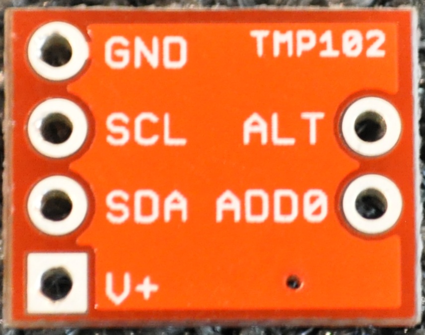
Sparkfun’s breakout board makes connecting it to the Raspberry Pi simple. There are six pins (or leads) coming off of the breakout. These pins are labeled on the back of the breakout board, and the ones you care about are on the left side.
The first pin is Ground (GND), the second pin is the Serial Clock (SCL), the third pin is the Serial Data Line (SDA), and the fourth pin is 5 V (V+). The SCL and SDA pins are how the sensor sends/receives data across the I2C bus.
You should not need to use the pins labeled ALT or ADD0 (they’re on the right side of the breakout board), unless you already have a conflicting device on the same I2C bus and need to change the device number. Because this is the only device on the Raspberry Pi GPIO I2C bus for this hack, you can just leave those pins alone. You can see these labels on the TMP102 device, as shown in Figure 4-3.
But the Datasheet Says…
If you happen to look at the datasheet provided by Sparkfun, you might notice that its numbering is different from what we’ve provided. It numbers the pins as they come off the TMP102 sensor itself, not as they appear on the breakout board. The TMP102 sensor is that tiny black chip in the middle of the breakout board. If you look closely (possibly with a magnifying glass), you’ll see the leads coming off the TMP102 to the breakout pins. The ordering is different, but the breakout board labels make a lot more sense to use, so we use those instead.
The mapping of the TMP102 breakout pins to the Raspberry Pi GPIO is fairly obvious, as shown in Table 4-1.
| TMP102 Breakout Pin Label | Raspberry Pi BCM GPIO Pin |
GND | GND |
SCL | 3 (SCL) |
SDA | 2 (SDA) |
V+ | 5 V |
Remember, the mapping in Table 4-1 referes to the BCM GPIO pin labels. See [Hack #14] if this doesn’t make sense to you.
To connect this device to the Raspberry Pi, you’ll first need to solder wires to the TMP102 breakout pins that you are using (GND, SCL, SDA, and V+).
See Soldering Reminders for some basic soldering tips.
If you are lazy, you can use male jumper wires and bend them tightly to make the connection, but this is really sloppy and hackish, even for a Hacks book. Either way, once you have wires coming off the TMP102 breakout, you need to connect them to the Raspberry Pi. You can either use jumper wires to connect directly to the appropriate GPIO pins, or you can use a Pi Cobbler and a breadboard for the simplest wiring (see [Hack #15] for more about the Pi Cobbler).
To use your TMP102 sensor (and make sure it is working on the Raspberry Pi I2C Bus), you need to install some software. To install i2ctools and lm-sensors, run the following command on Pidora:
$su -c'yum install i2c-tools lm_sensors -y'
On Raspbian, run:
$su -c'apt-get install i2c-tools lm-sensors'
Now, let’s try to find your device on the Raspberry Pi’s I2C Bus. To look for the device, you need to run i2cdetect on bus 1. On the original Raspberry Pi Model B units, this was bus 0, but with the current hardware, it is bus 1. Bus 0 actually exists on the current Raspberry Pi Model B, but you have to connect to it via the camera connector. Here’s the i2cdetect command line you want to run:
$su -c'i2cdetect -y 1'
You should see output like this:
     0  1  2  3  4  5  6  7  8  9  a  b  c  d  e  f
00:          -- -- -- -- -- -- -- -- -- -- -- -- --
10: -- -- -- -- -- -- -- -- -- -- -- -- -- -- -- --
20: -- -- -- -- -- -- -- -- -- -- -- -- -- -- -- --
30: -- -- -- -- -- -- -- -- -- -- -- -- -- -- -- --
40: -- -- -- -- -- -- -- -- 48 -- -- -- -- -- -- --
50: -- -- -- -- -- -- -- -- -- -- -- -- -- -- -- --
60: -- -- -- -- -- -- -- -- -- -- -- -- -- -- -- --
70: -- -- -- -- -- -- -- --
This is a graphical way of telling you that there is a device on I2C bus 1, with the numeric identifier 48. This is your TMP102 sensor.
You now know that our TMP102 device is device number 48 on I2C bus 1, but you need to tell the Linux kernel that it exists:
$su -c'echo tmp102 0x48 > /sys/class/i2c-adapter/i2c-1/new_device'
At this point, you are ready to start reading temperature data from your TMP102 sensor. The standard tool for doing this in Linux (lm_sensors) comes with a library (libsensors) that lots of tools support, but as a beginning point, you are going to use the included sensors command:
$sensors bcm2835_thermal-virtual-0 Adapter: Virtual device temp1: +42.8°C tmp102-i2c-1-48 Adapter: bcm2708_i2c.1 temp1: +24.8°C(high=+160.0°C,hyst=+150.0°C)
In this output, you can see two readings:
-
bcm2835_thermal-virtual-0 -
This is the temperature sensor inside the Broadcom BCM2835 system on chip at the heart of the Raspberry Pi. It is also the same reading you can get from
vcgencmd, as described in Measure Temperature. -
tmp102-i2c-1-48 - This is your TMP102 sensor, reporting for duty.
From this output, you can see that your TMP102 sensor is reporting a lovely temperature of 24.8°C. The high value is the value at which the TMP102 shuts down due to extreme overheating (160.0°C qualifies).
It also has a hyst value, which refers to “temperature hysteresis limit” (sadly, not Def Leppard’s legendary 1987 album Hysteria). The hysteresis limit value is the value at which the sensor reading no longer fluctuates, as it approaches the shutdown temperature.
If you just want to see the TMP102 reading, you just need to pass the lm_sensors “chip name” for that device as an option. As configured, the TMP102 is tmp102-i2c-1-48 ($sensortype-$bustype-$busnumber-$devicenumber). If you want to see the values in Fahrenheit, just pass -f:
$sensors -f tmp102-i2c-1-48 tmp102-i2c-1-48 Adapter: bcm2708_i2c.1 temp1: +76.5°F(high=+320.0°F,hyst=+302.0°F)
If you want to parse the sensor values directly, you can either use the aforementioned libsensors library, or you can access the values directly via /sys. /sys/class/i2c-dev/i2c-1/device/1-0048/ is the device node where you can find the values stored in special /sys files. These files represent the values reported from the device driver, and are updated constantly. If you want to get an updated value, just reopen one of these files:
$cd/sys/class/i2c-dev/i2c-1/device/1-0048/$ls driver modalias power temp1_input temp1_max_hyst hwmon name subsystem temp1_max uevent$cat temp1_input 23312
To convert that value to Celsius, just divide it by 1,000. If you need to convert it to other temperature units, refer to Fun with Math and Science.
Hack 38. Check on Your Plants
Plants are an important part of the ecosystem of life on our planet. Or maybe you just want tasty toppings on your burger. Either way, you can use your Raspberry Pi to help them grow big and healthy.
Gardening is tricky stuff. Plants can’t talk, so they can’t tell us what they need. Gardeners are like hackers in a lot of ways: they learn a lot by doing, getting experience in how to grow plants, where to keep them, how much to feed them, and what songs they like to listen to (hey, I heard they love music). At the heart of this, whether they realize this or not, is data gathering. By adding a dedicated temperature and humidity sensor to a Raspberry Pi, we can gather useful data about the state of the garden.
Most plants need a few things to grow properly:
- Soil
- This supports the plant and gives it an anchor for the roots to grow in. The roots draw in the water and minerals that the plant needs. You want to use a healthy, well-nourished soil with the right sort of minerals and ingredients for your plant. Potting soil is usually a good start, but there are much larger books about getting the perfect soil for your plant.
- Sunlight
- Plants perform photosynthesis, which is the process of converting sunlight into the chemical fuels to “power” the plants biological processes. All green plants need light, but the amount varies by plant. Some plants prefer a lot of of light, and some plants prefer much less.
- Air
- Specifically, carbon dioxide. If the air near your plant is too polluted, your plant will not grow well.
- Water
- Everything alive (that we know of) needs water. Plants are no different, but the amount of water that a plant requires varies by the type of plant. If this is confusing to you, think about a cactus in the desert and then compare it to a palm tree next to an oasis. Both are plants, both need water, but the cactus needs far less to survive (and wouldn’t really be able to use more than a little anyway).
- Space
- Plants need space to grow, usually up, but sometimes outward.
- Optimum temperature
- Again, this is specific to the type of plants, but all plants have a range of temperatures that they prefer. The U.S. Department of Agriculture calls this “plant hardiness” and maps it out into zones across the United States. Each zone is indicated by the range of temperatures it experiences, and each zone is given an identifier code. For example, Tom’s plant hardiness zone is 5b, and Ruth’s is 7a. See http://planthardiness.ars.usda.gov for a map of all the U.S. zones (and to discover your zone). Also, some plants tolerate frost and freezing better than others, so depending on your plants, temperatures dropping below 0°C could result in plant death.
Measuring the space, soil, and air is not simple to do, but we can measure the amount of water in the air and the temperature of the garden. You can also measure the intensity of light near the plants using the light sensor in [Hack #42], but this hack will focus on monitoring temperature and water (humidity).
Serious Gardeners
If you’re a hardcore gardener, you might point out that while humidity is interesting, it is less interesting than rainfall measurement (assuming your garden is not in a water-controlled greenhouse). To get that, you need to wire up a rain gauge sensor.
There are several different rain gauge sensors on the market, but connecting them to a Raspberry Pi and getting the data is a bit more complicated. There are some 1-Wire rain gauge units, but the Raspberry Pi does not have a 1-Wire connector. You can get around that by building a circuit to connect it to GPIO (either via the w1-gpio driver or the I2C bus), or you can buy a 1-Wire-to-USB converter (like the Maxim Integrated DS9490R#).
From a software side, you can use OWFS to read the data from the 1-Wire device. This can get complicated quickly, so we’ll leave this as an exercise for the motivated and serious gardener. For the rest of us, we’ll start with humidity and work our way up.
While it is technically true that your plants are growing in real time, they are doing it so slowly that you have to watch them over long periods of time to see the growth. (Search YouTube for “time lapse of plants”; it is rather freaky and cool.) As a result, we do not need to have real-time measurements of temperature and humidity, so using a sensor like a TMP102 (as in [Hack #37]) is overkill. Instead, we can use an “all-in-one” temperature and humidity sensor. Adafruit has an excellent one from Adsong, the AM2302.
Here are the main reasons the AM2302 sensor is a good one for this hack:
- It is sealed up in a plastic body, which will help it be resistant to Mother Nature’s wrath. It also has a mounting hole, so you can attach it (either by hanging or screwing) in a secure location in your garden.
- It is a digital sensor, so it is accurate and simple to wire.
- It reads in new data every two seconds, which is nowhere near real time, but is more than sufficient for monitoring plants in a garden.
- It uses three wires, and only one wire for communication! This means that only three GPIO pins on your Raspberry Pi will be used (and only one general-purpose pin needs to be reserved).
In fact, the only real downside to using the AM2302 is that it does not (as of the time of this writing) have a native Linux kernel driver for it. This means that we cannot easily plug it into the lm_sensors infrastructure, as described in [Hack #37].
Adding the AM2302 to the Linux Kernel
The AM2302 has a DHT22 temperature-humidity sensor at its core. It should be rather simple for someone with a basic understanding of C and the Linux kernel to add a hwmon driver for the DHT22. If you’re looking for a good starter Linux kernel development project, this might be it! We hope that one day this note will become obsolete once someone writes this code, and then this hack becomes much simpler for everyone!
Again, Adafruit comes to the rescue. They provide an open source C program for reading the temperature and humidity values off the AD2302. We’ll get to that in a moment, but first, you’ll want to wire it to your Raspberry Pi. The AD2302 has three wires coming out of the plastic case:
- Red
- For 3.3 V power
- Black
- For Ground (GND)
- Yellow
- Where the data comes out
Technically, you can connect any of the generic I/O pins on the GPIO header and it will work, but we know you’re going to ask us to tell you which pin to use … so just go ahead and connect the yellow data wire to BCM Pin 4 (P1-07). Why? Well, it is the first generic I/O pin underneath the 3.3 V (the two pins above it are I2C pins).
Connect the red wire to the 3.3V power pin (P1-01) and the black wire to a Ground (GND) pin. If you aren’t sure what all of these GPIO terms mean, check out [Hack #14]. The simplest way to wire these pins to the Raspberry Pi is with a solderless breadboard and a Pi Cobbler ([Hack #15]). The wires coming from the AD2302 are a little too thin to insert into the breadboard, so you’ll probably want to connect them directly to some thicker wire first. There are a number of ways to do this:
- Solder the wire to a thicker wire.
- Twist the ends of the two wires together, then seal them with electrical tape (or hot glue).
- Crimp the wires together using a crimping tool.
No matter which method you use, you’ll probably need to strip off some of the insulated connector covering the wires. You really should use a wire stripper for this, and not try to use a pair of scissors (or the cutting part of a pair of pliers), because you run the risk of cutting off part of the wire itself.
Once you have these three wires connected and properly inserted into your breadboard (with a Pi Cobbler connecting it to your Raspberry Pi GPIO ports), you can install the software to test it out.
On your Raspberry Pi, clone a copy of the Adafruit Git Raspberry Pi repository:
$git clone git://github.com/adafruit/Adafruit-Raspberry-Pi-Python-Code.git$cdAdafruit-Raspberry-Pi-Python-Code/Adafruit_DHT_Driver
Even though the name of this repository is Adafruit-Raspberry-Pi-Python-Code, you will notice that the code in this directory is in C. Adafruit had to use C code to talk to the AM2302 sensor since it requires extremely fast timing to read, and Python would not be able to easily accomplish this task.
Adafruit includes a precompiled binary that should work on any distribution of Linux for the Raspberry Pi, but if you do not trust their binary (or it doesn’t work for some reason), you can rebuild it. Just have gcc and make installed, and run:
$rm -f Adafruit_DHT$make Adafruit_DHT
Either way, you need to run the Adafruit_DHT binary. To talk to the AM2302 sensor on BCM Pin 4, run:
$su -c'./Adafruit_DHT 2302 4'Using pin#4Data(40): 0x2 0x16 0x0 0xe6 0xfeTemp=23.0 *C,Hum=53.4 %
The first option passed is the sensor type (this code also supports interfacing with a raw DHT11 (11) and DHT22 (22) in addition to the AM2302 (2302)). The second option is the GPIO pin that it is connected to. You can see that it is reporting a temperature of 23.0°C and a humidity of 53.4%.
You now have a reliable way of measuring the data from the AM2302. Adafruit has also included a Python script (Adafruit_DHT_googledocs.ex.py), which will run the Adafruit_DHT binary every 30 seconds, and upload the humidity and temperature readings into a Google Docs spreadsheet.
To use it, you will need to configure the script with your own Google Docs account details. Open Adafruit_DHT_googledocs.ex.py with your favorite text editor and then look for this section of code:
# Account details for google docs='you@somewhere.com'password='$hhh!'spreadsheet='SpreadsheetName'
Change the values for the email, password, and spreadsheet, making sure to keep the actual values wrapped in single quotes, and save out the file. To run the script, simply execute it from a terminal:
$ ./Adafruit_DHT_googledocs.ex.pyYou might want to run this in a screen session, so that you do not need to keep that terminal open. To do that, simply execute the screen command before running the Adafruit_DHT_googledocs.ex.py script, and then press Control-A-D to disconnect from the screen session. You can reconnect to that screen session later by running screen -r.
You can now go to your Google Docs account in a web browser and watch the humidity and temperature data for your plants get uploaded over time.
This is a simple monitoring setup, but it is possible to make more complicated setups using this model:
- You could write a wrapper script to check for alert conditions (temperature approaching freezing) and have it send you notification emails (or tweets).
- You could use the AM2302 as a data source for automating your garden (think automated watering).
- Or if you really don’t like plants, it could be part of a homemade weather station. Monitoring home-brewed beer or your wine cellar?
Really, anything that doesn’t handle temperature or moisture well is ideal for this hack.
Hack 39. Make Your Pi Water-Resistant (with a Case)
If you want to run your Raspberry Pi outdoors, you’re going to need to put it in a water-resistant case. Here’s one way to do it.
If you are working on a project that involves readings from the great outdoors, the best place for your Raspberry Pi is inside, but that isn’t always practical or possible. Whether you are trying to monitor plants in a garden, or automating your mailbox, you’ll need to protect your Raspberry Pi from:
- Water
- This includes, but is not limited to, rain, snow, sleet, hail, dew, sprinkler, and animal … fluids.
- Nature
- Dirt doesn’t hurt children, but it is no friend to electronics. Lots of animals like warmth, and the Raspberry Pi is an oasis of heat in a cold night. Also, the combination of nature and water means mold and mildew, neither of which is good for your Pi. Oh, and insects, we can’t forget them.
- Weather
- We’re not too worried about a tornado or a hurricane here. If that happens, you’ve got bigger problems than a broken or missing $35 Linux PC. That said, we don’t want it to fly away or break in normal weather conditions.
Here’s how to build a water-resistant, outdoor-friendly case for your Raspberry Pi. Start with a water-tight plastic container and lid (or, if you want to really up your game, get an ammo box with a rubber O-ring seal from an Army-Navy surplus store instead). We recommend getting a large one, as opposed to the smallest one the Raspberry Pi will fit completely into.
The plastic container will serve as a general protection from most of the main concerns highlighted earlier. Using a larger container will allow you to weight it down from the inside as needed and also gives it a bit more of an air pocket for the heat generated by the Raspberry Pi to dissipate outward.
You’ll probably want to connect cables to the Raspberry Pi, so you’ll need to make some holes in the container. Try to make these as small and as few as possible, but don’t just make one big hole and run all of your cables through it.
The trick is to make a hole, run a cable through it, and then use common silicon sealant (available at any large hardware store) to permanently seal the cable into the hole and restore the watertight seal for the plastic container. The trouble with this arrangement with multiple cables in the same hole is that it can be tricky to completely seal the gaps that occur between the cables. Also, if you opted for the metal ammunition box, you’ll need to get specialized sealant for metal (and a pretty good drill setup to make the holes).
Using a large container also gives you the opportunity to connect the USB power plug directly to a weatherized extension cord inside the container. Then, you can seal the extension cord through the hole, and the USB power plug is not exposed to the elements at all.
Since this arrangement is good, but not perfect (and it will condense some), go ahead and toss in several silica gel packets. This can be purchased rather cheaply from a variety of sources (including Amazon). The silica will dry out the air inside the container even further, and it is nontoxic.
Silica gel packets usually contain the warning not to eat them because of silica’s extreme dessicant nature and the fact that it is commonly doped with other chemicals that allow it to visually alter its color as it takes on moisture. Those chemicals are usually carcinogenic.
Also, depending on how waterproof (or animal-proof) you want the case to be, you can take the extra step of sealing the container lid into place “permanently” when you’ve finished.
We recommend that you consider wiring a temperature sensor (and possibly a humidity sensor) inside of this container case in addition to any external sensors or input/outputs (see Hacks [Hack #37] and [Hack #38] for details).
And as a bonus idea, you could also use this hack as the basis for a more elaborate Raspberry Pi-powered interactive geocache (as described in [Hack #41]).
Hack 40. Make Your Pi Water-Resistant (Without a Case)
Have you ever wanted to run your Raspberry Pi underwater without a case? This hack can make that happen (at least for a while).
Normally, electronics of any sort coming into contact with water results in the release of the magic smoke and one dead electronic component. Electronics used in the same environment as water are carefully sealed in watertight components (think about underwater cameras for example), but the Raspberry Pi is just a bare electronics board.
You could make it water resistant with a case (as described in [Hack #39]), but that can get expensive, and at the time of this writing, there were not many water-resistant cases for the Raspberry Pi out there. You could seal the entire Raspberry Pi in transparent resin, but that isn’t something most people have immediately available.
Safety Warning and Disclaimer
This hack is not for the faint of heart. It could very well result in a dead Raspberry Pi and some serious pain. It goes without saying that the Raspberry Pi is not designed or intended for use in water. By mixing electricity and water, you expose yourself to a very real risk of electrocution. Unless you are really prepared to undertake this hack safely, you might consider skipping it and moving on to something else. We don’t want you to hurt yourself. No hack is worth injury.
Enter NeverWet. NeverWet is a spray-on paint-type product from Rustoleum that, when applied to a surface, makes it extremely hydrophobic (as the name implies). The NeverWet paint applies a coating that causes water to form nearly perfect spheres, which roll off the surface, keeping items dry and clean. In the United States, you can find it in home improvement stores for $20. It comes in a box with two spray cans. The first is a primer, and the second applies the super-hydrophobic layer.
What Rustoleum Thinks About This Hack
We feel at this point we should tell you what Rustoleum thinks about using NeverWet on electronics. From their FAQ page:
Q: Can NeverWet be used on electronics? A: No, NeverWet should not be used on electronics.
OK, you’ve read that, right? Rustoleum isn’t interested in hearing about how this hack didn’t work for you or how you destroyed a $35 mini-computer. (For the record, we aren’t interested in hearing about it either.) All righty then, let us continue. Regardless of what the FAQ says, we know this works (at least for a while). We’ve done it.
There is an aesthetic downside to this hack. The NeverWet paint is not transparent, not even a little bit. When it dries, it looks like someone has applied a chalky white film over the surface of the Raspberry Pi. (Because you actually did by spraying it repeatedly with NeverWet paint.) It looks weird, to say the least.
Here’s what you’ll need for this hack:
- A Raspberry Pi that you have no sentimental attachment to. You’re never getting that $35 back.
- An SD card that you never plan on using again. We recommend a full-sized SD card, not a mini card in a converter, since that just adds another crevice for water to try to get in.
- Cables that you never want to use again. We used a USB power cable and a USB to TTL serial console cable, as the bare minimum to access the Pi, but you might want to add an Ethernet and HDMI cable into the mix or a WiFi dongle.
- One package of NeverWet spray paint.
Go to a dry, cool, still, well-ventilated place with your supplies. (We went with “the backyard on a nice fall day.”) You should already have your SD card configured with a Linux image. If you’re using a console over the UART serial device, have that properly configured as described in [Hack #16].
Firmly and completely insert your SD card and the cables you want to use. Make sure the system works right now, then leave all the cables connected to the Raspberry Pi, but disconnect the other ends from everything (like electricity!).
Now get out the NeverWet paint. The paint comes with instructions, but here’s the basic workflow:
- Prep your Raspberry Pi and cables for painting. We hung the Raspberry Pi in midair using the attached cables, but you might want to set it down on a table. Generally, dangling electronics from their cables is a bad idea, but in the name of a solid coat, we’ll let it slide this time.
- Shake can #1 (the primer) for a few minutes.
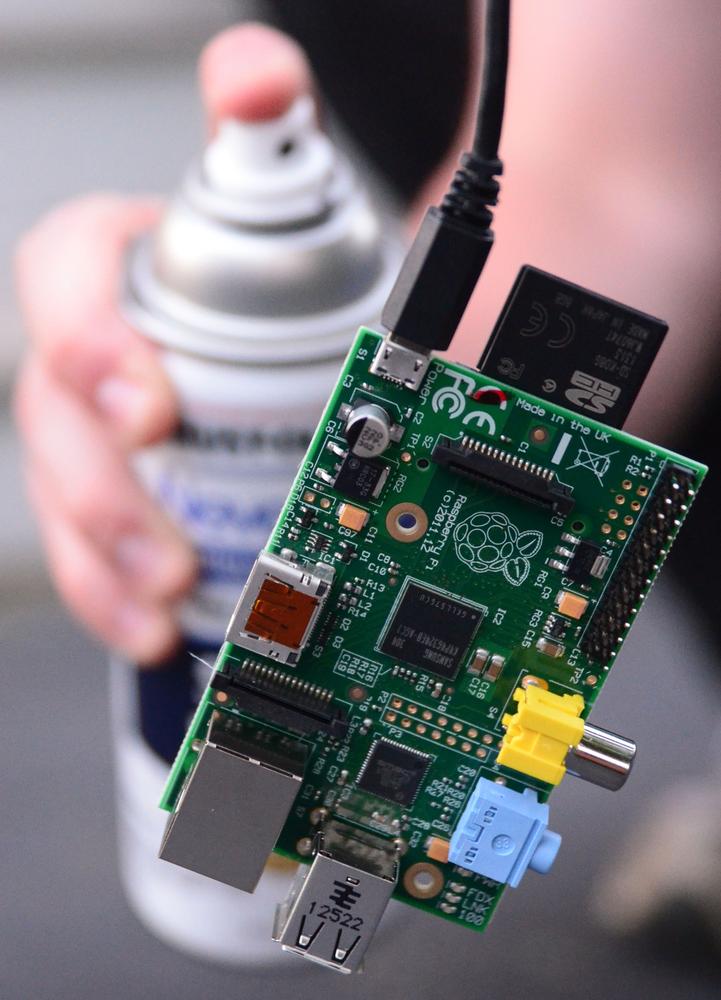
- Holding the can 6–12 inches away from the Raspberry Pi, apply a quick (but complete) coat of the NeverWet primer to ALL exposed surfaces, including a few inches on each cable, as shown in Figure 4-4. Spray inside every possible nook and cranny you can, including connectors you are not using and all around each connector you are using. Don’t forget to spray the edges and the GPIO pins.
- Let the primer dry for 30–60 minutes.
- Shake can #2 (super-hydrophic paint) for a few minutes.
- Repeat the process you used with the printer for can #2. Be thorough, but don’t waste paint. You want a solid coating on every possible surface that might contact water, but you don’t want to end up with a drippy mess. You want to be making smooth passes with the spray paint.
- Let it dry for five minutes, and then apply another layer of the paint in can #2. You want to repeat this cycle 3–4 times.
- When you’ve put on all the layers, let the Raspberry Pi dry for 12–24 hours.
After the last drying period, your Raspberry Pi is ready to use again. Power it up to make sure that the act of painting it with NeverWet didn’t kill it before it ever hits the water.
If you are planning to to immerse your Raspberry Pi in water, you should not hold it with your bare hands (for what we hope are obvious safety reasons). You should be able to gently insert it by holding the cable and lower it into a small container of water (either powered on or off). If you insert it into the water before powering it on, you might want to be a good distance away before sending power over to the Raspberry Pi. Having the Pi plugged in via a USB power cable run to a power strip (that is switched off) might be a good idea, since you can turn on the power strip from a distance. Additionally, whenever there is a risk of water, you should consider having a Ground Fault Circuit Interruptor (GFCI) in use. You can get this built into your power strip, or as an adaptor for the plug.
This is not a magic spell. It might not work at all. If you didn’t do a thorough paint job, it might immediately go “zap” and die. Heck, it might do that even if you do the best paint job known to mankind.
That said, even if you do manage to make a Raspberry Pi water-resistant using this method, you shouldn’t assume you can put it in a fish tank on your desk and use it forever. The coating isn’t permanent; it will fade with time and friction. Rustoleum notes that NeverWet relies on a layer of air to form the super-hydrophobic coating on the surface of the object. This means if you submerge a treated object over time, the coating will dissipate.
If you are putting a Pi in a space where humidity is a real possibility, this might be a good insurance against occasional humidity ending your project in heartbreak. However, we admit that in most cases, this is just a fun hack that allows you to say that you’ve run Linux in a computer completely underwater with no case.
Hack 41. Find Geocaches from Your Car
Geocaching is a great way to be geeky and get outdoors. Why not convert a Raspberry Pi into a Cacheberry Pi?
Geocaching taps into the thrill of finding something hidden, of going on a treasure hunt. If you’ve never heard of geocaching before, the idea is simple. People hide a storage container somewhere publicly accessible (although not necessarily easily accessible) and upload the GPS positioning coordinates for that container to the Internet.
The size of the container varies from the very small (just large enough to hold a miniature pencil with a tiny sheet of paper rolled around it), to small (35 mm film canister or Altoids tin), all the way up to large containers such as metal ammunition boxes. These are then hidden in plain sight, such as attached under park benches, hanging from trees, or in the crevices between rocks. One particularly memorable geocache is secured inside a large hollow tree by a tension pulley system. You reach inside the tree, pull a ring, and the geocache would drop down. Pull the ring again, and the cache goes back up inside the tree.
The ideas behind geocaching are not new by any means; people were doing real-world treasure hunts in the form of letterboxing for years beforehand. But when GPS was made available to the public in 1991, followed by the ubiquity of highly accurate GPS systems and the explosion of the Internet, geocaching-type treasure hunting was able to flourish.
At the time of this writing, http://geocaching.com (the primary website for logging and adding geocaches) is tracking more than two million active geocaches and more than six million registered geocachers. It is a game that can be played by people of all ages and abilities, with nothing more than a smartphone and tenacity. The rules of the game are simple: find as many as you can, be discreet when finding caches, leave the cache better than you found it, and log your finds (or failure to finds) so that the cache’s activity can be tracked.
There are other complexities:
- Exchange items
- Goodies, trinkets, toys, and “treasures” are left by geocachers in caches of supportable sizes. The rule of thumb is that if you take one, you also leave one behind.
- Travel bugs and geocoins
- Tracked objects that move via geocachers from cache to cache.
- Travel bug hotels
- Geocaches specifically set up to facilitate the drop-off and retrieval of travel bugs. These are usually found near transportation hubs, such as airports, so that geocachers can help travel bugs move around the world.
- Puzzle caches
- Geocaches where the GPS coordinates must be decoded from a puzzle.
- Multi-stage caches
- Sequences of caches where only the first set of GPS coordinates are provided, and each cache provides another set of GPS coordinates until they lead you to the final cache (usually a much larger cache with tradable goodies).
While there are any number of smartphone applications (or add-ons for in-car GPS systems) to help you find geocaches near you, Jeff Clement created the Cacheberry Pi (Figure 4-5) to be embedded in a car. This Raspberry Pi-based project is primarily intended to show you what the next nearby geocache is in a big, obvious way (as opposed to staring at little icons on a general-purpose GPS). It empowers you to not have to do as much prep before setting out to go geocaching by letting you simply get in your car, pick a direction, and drive.
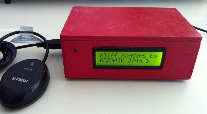
This hack is also smart about how it presents geocaches to you. When still, it presents the nearest cache in a 3 km radius. When the Cacheberry Pi detects that you are traveling at highway speeds, it will instead focus its search in front of you and show you only the nearest geocache in the direction that you are traveling. It has the ability to maintain a database of 20,000+ geocaches and to track a log of which caches you have visited (and allow you to transfer that log via USB storage device). It displays the nearest geocache to you, the distance to that cache, and the compass bearing to the geocache.
Gathering Hardware
To build the Cacheberry Pi, you will need some hardware in addition to the Raspberry Pi unit.
GPS receiver
The Cacheberry Pi project assumes that you are using a USB-powered GPS receiver (GPSr) and recommends the Holux M-215, but any other standards-compliant GPS should work properly.
You can also use the Adafruit Ultimate GPS Module, but if you do that, you will need to disable the serial console so that the GPS can use it (as covered in [Hack #16]). If you choose this hardware, you will also need to reconfigure gpsd within the Cacheberry Pi Linux OS to point to the serial GPSr by running:
$ sudo dpkg-reconfigure gpsdThis step is not necessary if you use a supported USB-powered GPSr.
LCD screen
The LCD screen is where the Cacheberry Pi will present geocache information to you while you’re on the hunt. The Cacheberry Pi project recommends the IIC/I2C/TWI SPI Serial LCD 1602 Module Electronic building block for Arduino.
You can also use the Sainsmart 1602 ICD LCD unit, but you will then have to modify the driver in the Cacheberry Pi codebase. Steve Whitcher has documented how he was able to get it working.
It might also be possible to use other 16 x 2 LCD units (such as the one on the Adafruit LCD Pi Plate, covered in [Hack #28]), but we have not tested them.
Power cord
Because the Cacheberry Pi is designed to be used in an automobile, you can plug it into an available 12 V power (cigarette lighter) receptacle. [Hack #55] covers this sort of power arrangement in detail.
Since the only device normally plugged into the Cacheberry Pi USB bus is the GPSr (and a USB flash drive when updating the geocache database), you should not need to use an externally powered USB hub.
Serial console
This is optional (and not available if you are using the Adafruit Ultimate GPS Module), but the Cacheberry Pi is configured by default to support a serial console over the Raspberry Pi GPIO pins.
If you want to add a serial console, just follow the instructions in [Hack #16], and make a hole in the project box for the wire to come out.
Indicator LED
You can optionally connect an indicator LED. It will flash when a geocache is nearby, but you don’t really need this unless geocaches are few and far between in your part of the world (or you only have a few in the Cacheberry Pi database).
Project box
Admittedly, this is purely an aesthetic component, but you can get a standard plastic project box, cut a hole for the LCD to mount, then place the Raspberry Pi inside of the box as well. Holes for the power cable and both USB ports will finish off the box, then you can attach your finished Cacheberry Pi (in a box) to the dash of your car.
Preparing the Software Image
The Cacheberry Pi project offers a prebuilt image (based on Raspbian). Put a fresh SD card into your Linux computer, and then download and uncompress a copy of the Cacheberry Pi image:
$wget http://cdn.jclement.ca/cacheberrypi/cacheberrypi.img.20120921.bz2$tar xf cacheberrypi.img.20120921.bz2
By the time you read this, there might be a newer image than the 2012-09-21 image. You can confirm on the Cacheberry Pi project website.
After it downloads sucessfully, use the dd command to write the Cacheberry Pi image onto the SD card. Be extra careful that you know which device is your inserted SD card ([Hack #2] explains how to figure that out). In Fedora, this is almost always /dev/mmcblk0, but on other distributions it is a /dev/sd* device. You do not want to use dd to overwrite your laptop’s hard drive with the Cacheberry Pi image!
Once you’re sure you know the SD card device name, run the dd command as root, changing the of= value as needed:
$sudo ddbs=4Mif=cacheberrypi.img.20120921of=/dev/mmcblk0
When that finishes, run the sync command a few times to ensure the image was properly written onto the SD card (and not just into the memory buffers):
$ sync;sync;syncFinally, remove the SD card from your laptop and insert it into your Raspberry Pi.
Wiring the Cacheberry Pi
This hack assumes you are using the components recommended by the Cacheberry Pi project. If you differ from them, you will need to adjust accordingly.
Plug the USB GPSr directly into a USB port on the Raspberry Pi. The LCD screen has four pins, labeled SCL, SDA, VCC, and GND. You will need to connect these pins to the appropriate pins on the Raspberry Pi GPIO using female-to-female jumper wires. Table 4-2 shows the pin mapping.
| Cacheberry LCD Pin Label | Raspberry Pi BCM GPIO Pin |
GND | GND |
SCL | 3 (SCL) |
SDA | 2 (SDA) |
VCC | 5 V |
If you want to connect an indicator LED, wire it into BCM Pin 25 (P1-22), with an appropriate resistor between the BCM 25 pin and the positive leg of the LED. The type of resistor will depend on the specifications of the LED being used. For example, if you use a Red LED with a voltage of 2 V and a current of 15 mA, the 5 V circuit will require a 220 ohm resistor. You can calculate the resistor value for your LED with this website: http://led.linear1.org/1led.wiz The negative leg of the LED should wire to an available GPIO ground (GND) pin.
Connect the Raspberry Pi to the mini-USB power cable (fed from the 12 V cigarette lighter receptacle), and the OS image should boot up.
Loading Cache Data
Because the Cacheberry Pi is not networked, you need to load geocaches via a USB flash drive. It is configured to always listen for a USB drive to be inserted, and when one is inserted with the proper filesystem layout, it will automatically import the geocache database off of the USB drive. It will also copy the track history from the Cacheberry Pi to the USB flash drive.
To set up a USB flash drive, insert it into your Linux computer and make sure it is mounted. Most Linux distributions will automount USB storage devices when they are inserted. Check the output of the mount command for a /dev/sdb or /dev/sdc device (/dev/sda is usually the laptop hard drive), and then change into the directory where the USB drive is mounted.
Download and decompress the “sample” ZIP file for the Cacheberry USB filesystem layout. Then copy the files into the mounted USB drive (in this example, we assume it is mounted at /mnt/usbdrive):
$cd~$wget http://cdn.jclement.ca/cacheberrypi/cacheberrypi_usbstick_sample.zip$unzip cacheberrypi_usbstick_sample.zip$cp -a cacheberrypi_usbstick_sample/* /mnt/usbdrive
The USB drive is now prepared for use, but you’ll want to add some cache entries. The Cacheberry Pi will look for a file named nav.csv in the cacheberrypi/ directory. This comma-separated values (CSV) file contains the list of geocaches in what is commonly referred to as “Microsoft Streets and Trips” format.
The simplest way to generate this CSV file is to run GSAK on Windows or Open Cache Manager on Linux/OSX. You can also generate a CSV file directly on http://geocaching.com if you have a premium account and set up a “pocket query.”
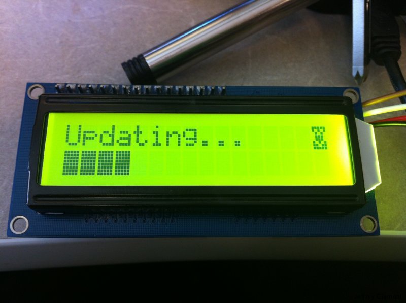
Save the nav.csv file to the USB flash drive, unmount it, and insert it into the running Cacheberry Pi. It should detect the USB flash drive, and the LCD screen will show a progress indicator as it copies over the updated geocache database (Figure 4-6).
Hack 42. See the Light
Detecting the presence (and intensity) of light can help you to automate all sorts of tasks, from the garden to home automation and beyond. Hack your Raspberry Pi and it will see the light!
Few things are constant in our world, but the rising and setting of the sun is close enough that you can count it as one, at least for the next five billion years or so. By monitoring the presence and intensity of light, you can tell whether it is day or night, whether it is sunny or cloudy, or if someone has turned on a lamp in a room. But to do that, you need a luminosity sensor.
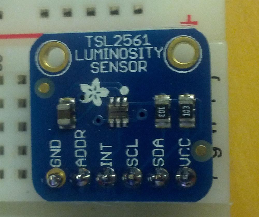
There are lots of different luminosity sensors out there, but because you want to wire it to our trusty friend, the Raspberry Pi, you want to pick something that you can add to that device easily. Because the Raspberry Pi does not support analog inputs (without going through a converter first), you need a digital luminosity sensor, with bonus points for one that the Linux kernel supports natively. Adafruit has just the thing: the Taos TSL2561 digital luminosity/lux/light sensor.
Why is this sensor ideal? A few reasons:
- It is a digital sensor, so you can connect it directly to the Raspberry Pi GPIO pins without any complicated wiring.
- It is precise and can be configured to detect light ranges from 0.1 to 40,000+ lux.
- It contains both infrared and full-spectrum diodes. Most luminosity sensors have only one type of detection diode, but the TSL2561 can separately measure infrared, full-spectrum, or human-visible light.
- It supports I2C (for an explanation of I2C, see What is I2C?). This means you can connect it to the Raspberry Pi GPIO with just four pins.
- It is a low-power component, about 0.5 mA when actively sensing and less than 15 uA when in powerdown mode.
- It is also small, about the size of a U.S. quarter (see Figure 4-7).
When you purchase the TSL2561 sensor kit, it comes with the light sensor already attached to a six-pin breakout board (and a six-pin header strip). Plug the header strip into a breadboard, with the long end of the header pins down, and then place the light sensor breakout board onto the header pins (the shorter ends). Solder the pins permanently to the breakout board (if you need a refresher on soldering, see Soldering Reminders).
Then, you’ll need to connect four of the six pins on the TSL2561 breakout board to the Raspberry Pi GPIO ports (see Table 4-3).
| TSL2561 Breakout Pin Label | Raspberry Pi BCM GPIO Pin |
GND | GND |
SCL | 3 (SCL) |
SDA | 2 (SDA) |
VCC | 3.3 V |
The TS2561 is a 3.3 V-powered device, so be sure you do not accidentally connect it to the 5 V power pin on the Raspberry Pi GPIO, or it will go off to electronics heaven. The Pi Cobbler makes this wiring notably simpler (see [Hack #15]), but as long as you have wires connecting the TSL2561 breakout to the right pins on the Raspberry Pi GPIO, you will be fine.
As usual, the instructions in this hack refer to the BCM GPIO pin labels here (see [Hack #14] for details).
Once the TSL2561 breakout board is wired up to the Raspberry Pi, you can use the I2C utilities within the Linux distribution environment to confirm it is properly connected to the I2C bus on the GPIO, assuming your kernel has I2C support properly configured. If you have built a custom kernel as described in [Hack #22], you will have I2C preconfigured properly. If not, you might need to load the following modules before you can access I2C devices:
$su -c'modprobe i2c-bcm2708'$su -c'modprobe i2c-dev'
Further, you will need to enable these additional options:
-
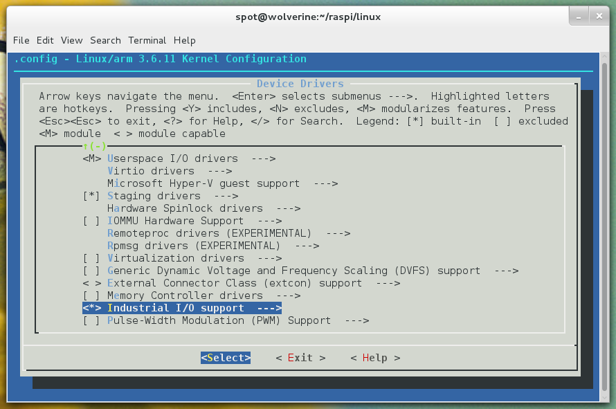
Industrial IO Support (
CONFIG_IIO) -
This option can also be found in the Device Drivers menu. The industrial I/O subsystem provides a unified framework for drivers for many different types of embedded sensors using a variety of different physical interfaces. You can also go into that menu and build support for any of the devices that you find within it that you might want to use in projects. Be sure that you compile in the top-level IIO support, as shown in Figure 4-8 (you can modularize the sensors below it if you wish). You will also want to be sure to enable (and compile in) the “Enable buffer support within IIO” (
CONFIG_IIO_BUFFER), “Industrial I/O buffering based on kfifo” (CONFIG_IIO_KFIFO_BUF), and “Enable triggered sampling support” (CONFIG_IIO_TRIGGER) options inside the Industrial IO Support menu.
-
TAOS light sensors (
CONFIG_SENSORS_TSL2563) -
This driver is currently in the
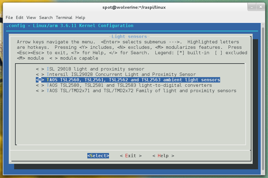
staginglevel of the Linux kernel device drivers, which is reserved for drivers that are new or less tested than other drivers. To enable it, navigate into the Device Drivers menu and then the Staging drivers menu (you will need to enable it first). From there, go into the IIO staging drivers submenu and then into Light sensors.CONFIG_SENSORS_TSL2563is labeled in that menu as “TAOS TSL2560, TSL2561, TSL2562 and TSL2563 ambient light sensors.” Enable it as a module, as shown in Figure 4-9. You will also need to enable “Hwmon driver that uses channels specified via iio maps” (CONFIG_IIO_ST_HWMON) to allow IIO devices to provide basic hwmon functionality. This entry is in the Device Drivers → Staging drivers → IIO staging drivers menu. You should compile this driver into the Linux kernel so that you automatically get this feature when you use IIO devices.
To install the necessary userspace software (i2c-tools) on Pidora, run:
$su -c'yum install i2c-tools -y'
To install i2c-tools on Raspbian, run:
$su -c'apt-get install i2c-tools'
To look for the device, you need to run i2cdetect on bus 1 (as root). Here’s the i2cdetect command line you want to run:
$su -c'i2cdetect -y 1'
If all of your wiring is correct, you will see output like this:
     0  1  2  3  4  5  6  7  8  9  a  b  c  d  e  f
00:          -- -- -- -- -- -- -- -- -- -- -- -- --
10: -- -- -- -- -- -- -- -- -- -- -- -- -- -- -- --
20: -- -- -- -- -- -- -- -- -- -- -- -- -- -- -- --
30: -- -- -- -- -- -- -- -- -- 39 -- -- -- -- -- --
40: -- -- -- -- -- -- -- -- -- -- -- -- -- -- -- --
50: -- -- -- -- -- -- -- -- -- -- -- -- -- -- -- --
60: -- -- -- -- -- -- -- -- -- -- -- -- -- -- -- --
70: -- -- -- -- -- -- -- --
The TSL2561 sensor reports as device address 0x39 on the I2C bus, and sure enough, i2cdetect sees it. If you want to change the device address, you can connect a wire to the ADDR pin on the TSL2561 breakout board. Connect it to a ground (GND) pin to set the address to 0x29, or connect it to a 3.3 V power pin to set the address to 0x49.
Accessing the Sensor via Python
The easiest way to get readings from the TSL2561 sensor is to use the Adafruit I2C Python module. The simplest value to understand from the TSL2561 is lux, but the TSL2561 doesn’t read in those units directly; you have to write code to do the mathematical conversion.
As a further complication, you can adjust the gain on the TSL2561 sensor. If the gain is set low (1), the sensor will calculate more accurate readings in bright light to avoid sensor saturation. If the gain is set high (16), the sensor will calculate more accurate readings in low light by boosting the sensitivity. You can also generate a reading with “automatic” gain, which cycles between low and high gain.
You will need to install the python-smbus and Adafruit_I2C libraries. The python-smbus library is included in the Pidora and Raspbian package repositories, so you can install it normally. Here’s the command for Pidora:
$su -c'yum install python-smbus'
And here’s how to install it on Raspbian:
$su -c'apt-get install python-smbus'
The Adafruit_I2C code is in the Adafruit Raspberry Pi Python Code GitHub repository. Check out a copy of it, and change into the Adafruit_I2C directory:
$git clone https://github.com/adafruit/Adafruit-Raspberry-Pi-Python-Code$cdAdafruit-Raspberry-Pi-Python-Code/Adafruit_I2C
From this directory, you can run a Python script to calculate the lux value measured by the TSL2561. This script was written by Ty Brown and is included here with his permission:
#!/usr/bin/pythonimportsysimportsmbusimporttimefromAdafruit_I2CimportAdafruit_I2C### Written for Python 2 <-!!!### Big thanks to bryand, who wrote the code that I borrowed heavily from/was inspired by### More thanks pandring who kind of kickstarted my work on the TSL2561 sensor### A great big huge thanks to driverblock and the Adafruit team (Congrats on your many succeses### Ladyada). Without you folks I would just be a guy sitting somewhere thinking about cool stuff### Now I'm a guy building cool stuff.### If any of this code proves useful, drop me a line at medicforlife.blogspot.comclassLuxmeter:i2c=Nonedef__init__(self,address=0x39,debug=0,pause=0.8):self.i2c=Adafruit_I2C(address)self.address=addressself.pause=pauseself.debug=debugself.gain=0# no gain preselectedself.i2c.write8(0x80,0x03)# enable the devicedefsetGain(self,gain=1):""" Set the gain """if(gain!=self.gain):if(gain==1):self.i2c.write8(0x81,0x02)# set gain = 1X and timing = 402 mSecif(self.debug):"Setting low gain"else:self.i2c.write8(0x81,0x12)# set gain = 16X and timing = 402 mSecif(self.debug):"Setting high gain"self.gain=gain;# safe gain for calculationtime.sleep(self.pause)# pause for integration (self.pause must be bigger than integration time)defreadWord(self,reg):"""Reads a word from the I2C device"""try:wordval=self.i2c.readU16(reg)newval=self.i2c.reverseByteOrder(wordval)if(self.debug):("I2C: Device 0x%02Xreturned 0x%04Xfrom reg 0x%02X"%(self.address,wordval&0xFFFF,reg))returnnewvalexceptIOError:("Error accessing 0x%02X: Check your I2C address"%self.address)return-1defreadFull(self,reg=0x8C):"""Reads visible+IR diode from the I2C device"""returnself.readWord(reg);defreadIR(self,reg=0x8E):"""Reads IR only diode from the I2C device"""returnself.readWord(reg);defgetLux(self,gain=0):"""Grabs a lux reading either with autoranging (gain=0) or with a specified gain (1, 16)"""if(gain==1orgain==16):self.setGain(gain)# low/highGainambient=self.readFull()IR=self.readIR()elif(gain==0):# auto gainself.setGain(16)# first try highGainambient=self.readFull()if(ambient<65535):IR=self.readIR()if(ambient>=65535orIR>=65535):# value(s) exeed(s) datarangeself.setGain(1)# set lowGainambient=self.readFull()IR=self.readIR()if(self.gain==1):ambient*=16# scale 1x to 16xIR*=16# scale 1x to 16xratio=(IR/float(ambient))# changed to make it run under python 2if(self.debug):"IR Result",IR"Ambient Result",ambientif((ratio>=0)&(ratio<=0.52)):lux=(0.0315*ambient)-(0.0593*ambient*(ratio**1.4))elif(ratio<=0.65):lux=(0.0229*ambient)-(0.0291*IR)elif(ratio<=0.80):lux=(0.0157*ambient)-(0.018*IR)elif(ratio<=1.3):lux=(0.00338*ambient)-(0.0026*IR)elif(ratio>1.3):lux=0returnluxoLuxmeter=Luxmeter()"LUX HIGH GAIN ",oLuxmeter.getLux(16)"LUX LOW GAIN ",oLuxmeter.getLux(1)"LUX AUTO GAIN ",oLuxmeter.getLux()
A copy of this script is also available in the GitHub repository for this book. Be sure you put this file in the Adafruit_I2C directory. To read the lux values, run:
$chmod +x tsl2561-lux.py$su -c'./tsl2561-lux.py'
This script does all of the hard work for you. It reads in the values from the sensor at the different gain settings and then does the math necessary to convert those values into lux units.
Accessing the Sensor Directly from the Kernel
It is also possible to interface directly to the TSL2561 sensor via the I2C bus at the kernel level, assuming you have enabled that support in a custom kernel (as described in [Hack #22]). First, you need to tell the kernel (as root) to attach the TSL2561 driver to the I2C device at 0x39 (or 0x29/0x49 if you changed the address with the ADDR pin):
$su -$echotsl2563 0x39 > /sys/class/i2c-adapter/i2c-1/new_device
When you do this, it will output a message like this to dmesg:
[522.400407]tsl2563 1-0039: model 5, rev. 0[522.402650]i2c i2c-1: new_device: Instantiated device tsl2563 at 0x39
There is a new device node (1-0039) in /sys/class/i2c-adapter/i2c-1/. Inside that node is a iio:device0 mapping, and inside that mapping directory are several devices that allow you to get readings:
$ls -l /sys/class/i2c-adapter/i2c-1/1-0039/iio\:device0/ ... -rw-r--r-- 1 root root 4096 Sep 16 20:37 in_illuminance0_input -rw-r--r-- 1 root root 4096 Sep 16 20:37 in_intensity_both_calibscale -rw-r--r-- 1 root root 4096 Sep 16 20:37 in_intensity_both_raw -rw-r--r-- 1 root root 4096 Sep 16 20:37 in_intensity_ir_calibscale -rw-r--r-- 1 root root 4096 Sep 16 20:37 in_intensity_ir_raw ...
These files contain the current raw sensor values for the calibration scale and the infrared and combined luminosity readings. To do anything with them, you’ll have to convert them using the math in the TSL2561 datasheet.
Hack 43. Listen to Aircraft Transponders
Every day, thousands and thousands of airplanes are flying the friendly skies. Some might be flying over you right now! With a USB TV tuner and a Raspberry Pi, you can listen to the aircraft transponders and find out which planes are up there.
An aircraft transponder is the device on board a plane that responds to radio frequencies and helps identify the plane for various systems, including radar. They generally send a few pieces of information, including altitutde, location, and what’s called a “squawk” code that further identifies the flights. If you want to listen to aircraft transponders, it will help if you’re within five miles of a local airport, but the occasional commercial plane passing by will be sufficient—you’ll just have more infrequent results.
- Raspbian
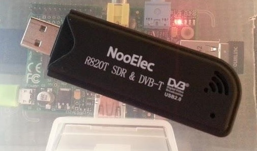
- NooElec R820T: these devices are easily found on eBay as well, but be sure you have the E4000 chipset variant. Look for “E4000” in the description to make sure your purchase will work with this project or refer to the list of supported hardware. This device is also called an RTL-SDR, or RealTek Software Defined Radio, because of the vendor of the analog-to-digital chip it uses. It looks like a flash drive (see Figure 4-10), but it is so much more.
- Dump1090: open source code for tuning the RTL-SDR hardware and decoding the data.
Extend Your Antenna
The antenna supplied with the NooElec R820T devices is pretty short. You can run a longer antenna over a window ledge, or to craft a more optimal antenna, see the tutorial at http://www.balarad.net. For most purposes, however, the NooElec’s included antenna will suffice.
Set Up the Code
To get started, update Raspbian and install the dependencies needed for building Dump1090:
$sudo apt-get update$sudo apt-get upgrade$sudo apt-get install git-core git make cmake libusb-1.0-0-dev build-essential pkg-config
Once finished, check out a copy of the source code of the drivers for the RTL-SDR device, and then build and install them on your Raspberry Pi:
cd/opt/ git clone git://git.osmocom.org/rtl-sdr.gitcdrtl-sdr sudo mkdir buildcdbuild sudo cmake ../ -DINSTALL_UDEV_RULES=ON sudo make sudo make install sudo ldconfig
Be aware that the build process that occurs during these steps will take several minutes on the Pi. The build script will update your status as it progresses.
When the install is complete, you need to copy a set of device rules for the RTL-SDR into the udev configuration directory:
$cd/opt/rtl-sdr/$sudo cp rtl-sdr.rules /etc/udev/rules.d/
These rules will ensure that your RTL-SDR device is properly configured when it is inserted into your Raspberry Pi.
If you haven’t already done so, go ahead and plug in your RTL-SDR device. Then, reboot the Raspberry Pi to ensure that the system cleanly and correctly loads the drivers on startup:
$ sudo rebootNow, you should run a test script to make sure Raspbian is using the driver and can receive data from the RTL-SDR device:
$ rtl_test -tIf all is well, happy messages will appear and test the modes of the RTL-SDR device:
$rtl_test -t Found 1 device(s): 0: Generic RTL2832U(e.g. hama nano)Using device 0: Generic RTL2832U(e.g. hama nano)Found Elonics E4000 tuner Supported gain values(18): -1.0 1.5 4.0 6.5 9.0 11.5 14.0 16.5 19.0 21.5 24.0 29.0 34.0 42.0 43.0 45.0 47.0 49.0 Benchmarking E4000 PLL...[E4K]PLL not lockedfor51000000 Hz![E4K]PLL not lockedfor2204000000 Hz![E4K]PLL not lockedfor1102000000 Hz![E4K]PLL not lockedfor1241000000 Hz! E4K range: 52 to 2203 MHz E4K L-band gap: 1102 to 1241 MHz
Let this run and finish if you like, or stop the test program with Ctrl+C.
Move back to the /opt/ directory to prepare Dump1090, our signal decoding script:
$cd/opt/
Then create the /dump1090 directory with Git:
$git clone git://github.com/MalcolmRobb/dump1090.git Cloning into'dump1090'... remote: Counting objects: 687,done. remote: Compressing objects: 100%(420/420),done. remote: Total 687(delta 411), reused 521(delta 259)Receiving objects: 100%(687/687), 712.00 KiB | 72 KiB/s,done. Resolving deltas: 100%(411/411),done.
Change directories into dump1090:
$cddump1090
Type make and press Enter. This too will take a little time as it compiles, so mark your spot in this tutorial and take a short break if you like. (We always support eating pie while building with the Pi.)
After make has finished, you’ll be just about ready to run the app. If you haven’t noted the IP address of your Raspberry Pi yet, do so now with ifconfig, which results in something like this:
eth0      Link encap:Ethernet  HWaddr b8:27:eb:81:54:dc
      inet addr:192.168.1.17  Bcast:192.168.1.255  Mask:255.255.255.0
          UP BROADCAST MULTICAST  MTU:1500  Metric:1
          RX packets:0 errors:0 dropped:0 overruns:0 frame:0
          TX packets:0 errors:0 dropped:0 overruns:0 carrier:0
          collisions:0 txqueuelen:1000
          RX bytes:0 (0.0 B)  TX bytes:0 (0.0 B)

lo        Link encap:Local Loopback
          inet addr:127.0.0.1  Mask:255.0.0.0
          UP LOOPBACK RUNNING  MTU:16436  Metric:1
          RX packets:17 errors:0 dropped:0 overruns:0 frame:0
          TX packets:17 errors:0 dropped:0 overruns:0 carrier:0
          collisions:0 txqueuelen:0
          RX bytes:2042 (1.9 KiB)  TX bytes:2042 (1.9 KiB)
The address after inet addr: will be the IP address you will use to view the plane traffic in a web browser after starting the script, which you’re ready to do!
Run the Script
Before running the script, move to the dump1090 directory:
$cd/opt/dump1090
Then, run the script:
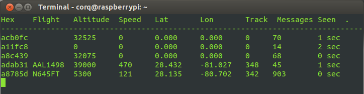
$ ./dump1090 --net --net-http-port 8080You won’t see much happen, but if you see no errors, the script is likely running, and if commercial planes are nearby, you will see an occasional stream of strange hex code. It might take a few minutes, but planes will transmit data from their beacon as they pass overhead, and when they do, you’ll begin to see lines in the script populate, as shown in Figure 4-11.
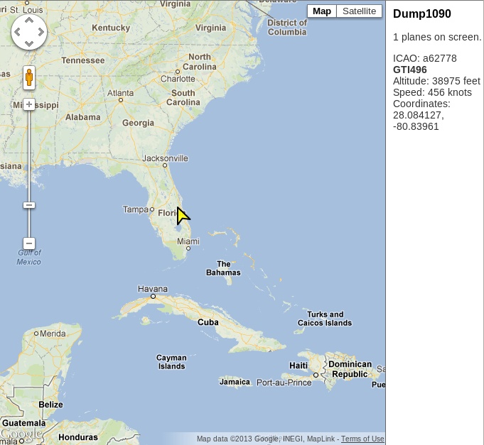
From another PC on your local network, open a web browser and enter the Pi’s IP address with :8080 appended (for example, http://192.168.1.17:8080). The first time you load this page, it will seem slow, because the Pi initializes the Google Maps API for the first time.
After a moment, you will see a handy map centered somewhere in Europe that looks a lot like Figure 4-12. Just drag it to focus on your own region or double-click on your area of the map until you’ve zoomed into the area where you are.
You can also define your actual latitude and longitude to get your map to center in your region (instead of Europe, if that’s not where you are) at startup. Visit http://itouchmap.com/latlong.html to pinpoint your location and note the coordinates. Use them to update script.js in /opt/dump1090/public_html/ with your actual location:
# find these lines below, update coordinates with the coordinates you got from the iTouch map page, making sure the lines end with the semicolon.varMap=null; varCenterLat=28.08864; varCenterLon=-80.609436;
Save the file and exit. The next time you run Dump1090, the web page will center on your region of the map.
—Lori Easterly
Hack 44. Control Aerial Photography
Aerial photography, particularly from nearspace altitudes, has gained popularity in recent years. The Raspberry Pi makes it even easier to achieve a low-weight payload with plenty of storage for photo, video, and data.
Aerial photography has been practiced since the mid-19th century when Gaspard-Félix Tournachon photographed Paris from a balloon. For some, it’s an art form. For others, there’s a distinct goal, such as when a group teamed with the Louisiana Bucket Brigade to map and document the Deepwater Horizon oil spill in 2010.
The recommendations in this hack are based on the launches by the NC Near Space Research group, which started as a group entering the Hackerspaces in Space contest, created in 2010 by Chicago hackerspace Workshop 88. They’ve since gone on to launch multiple balloons and found the Raspberry Pi to be a useful tool for such projects.
The Raspberry Pi takes half an amp of currrent. Why would you want to put that in the payload of a balloon where weight and size are critical? Because having it onboard will give you just about everything you need and a little more:
- Small and lightweight storage in an SD card for not only the “hard drive” and computing, but also for the storage of all the data and photography
- GPIO that can be used for a wide range of sensors, including an accelerometer, magnetometer, gyroscope, and temperature sensors
- Video out, so you can drive a video transmitter directly and see the video live on the ground, rather than waiting until after the payload is retrieved (that is, if the payload is retrieved)
- The ability to send on-screen display of the project’s current data while in flight, including its location and height
- An optional lightweight camera module designed specifically for the Raspberry Pi
- The ability to connect to a USB WiFi adapter for WiFi from space!
While not used on this project, the Raspberry Pi can also serve as a tracking device for finding the payload after it lands. The sound module on the Pi can generate a modulated APRS (Amateur Position Reporting System) data stream that can be fed into the transmitter and broadcast to ham radio operators, allowing you to track it live.
Thus a single, credit-card-sized device provides camera, data collection, tracking, and storage all in one incredibly cost-effective piece. When you add the prices of these components if built otherwise, the Raspberry Pi is both the cheapest and lightest way to go, which is handy, given what else you’ll have to buy.
For a near-space balloon photography project launch, you need the following major components in addition to the Raspberry Pi (which is a part of your payload):
- Balloon to lift the payload
- Parachute to bring it down safely
- The payload itself (contents described next)
- A tracking device to find it
Build the Payload
Your first step is to build your payload, because that’s the only way to find out how heavy it is. Knowing that piece of information is critical to figuring out what size balloon and parachute you’ll need and how much helium to lift it.
If you’re launching in the United States, you should keep your payload under four pounds, which keeps you from having to do further weight/size ratio calculations for the FAA (see note on FAA Regulations). You should also contact your local FAA office (or the relevant airspace organization for your country) prior to planning a flight to make sure you follow their recommendations for the design, launch, and retrieval of the payload.
FAA Regulations
In the United States, the relevant section of the Code of Federal Regulations is Title 14: Aeronautics and Space, Part 101: Moored Balloons, Kites, Amateur Rockets And Unmanned Free Balloons. Part 101.1(4), which describes the size limits of the payload:
- More than four pounds with a weight/size ratio of more than three ounces per square inch of any surface of the package (determined by dividing the total weight in ounces of the payload package by the area in square inches of its smallest surface)
- More than than six pounds (regardless of weight/size ratio)
- A payload of two or more packages that weighs more than 12 pounds
Before launching anything, you shuld read this section of the Federal Regulations in its entirety to be sure you comply.
You should first decide what you will use for you payload container. Whatever you choose, keep it light and waterproof. A styrofoam cooler is an easy and cheap solution, because you can make modifications with nothing more than a knife. Lightweight plastic containers are also useful.
Whatever you choose needs to be large enough to house the Raspberry Pi, a battery pack, your tracking device, and your camera(s), as well as any other parts you’ve chosen to use as a part of the project. (You can see how space and weight can add up!) The example payload in this hack includes the Raspberry Pi connected to:
- Video out to a 144 MHz Videolinx ham radio ATV (Amateur TV) transmitter and small whip antenna Trackuino which contains a GPS, and a 300 milliwat HX-1 144.39 MHz APRS transmitter, and an Arduino for decoding and modulating the GPS signal for the transmitter
- GY-80 I2C 9-Axis Magnetic Acceleration Gyroscope Module
- 5000 mAh USB cell phone backup battery
- USB WiFi adapter
- USB Y power cable to allow powering the WiFi directly from the battery and not through the Raspberry Pi’s weak USB power ports
- Raspberry Pi camera module
- Nikon Coolpix camera (controlled by gphoto)
The Trackuino is an Arduino-based APRS system that includes a high-altitude GPS system and GPS antenna. The Arduino decodes the data from the GPS and then modulates it to drive a 300 mW HX-1 transmitter, which then drives an 8 W Micro Amp 3 amplifier, which is then fed into a whip antenna. The amplifier isn’t necessary once your payload gets up high enough above the terrain, but it is helpful in locating the payload when it’s down on the ground and away from other ham radio APRS systems.
The Trackuino and Micro Amp3 are driven by eight AA lithium cell batteries (independent of the 5000 mAh cell phone battery that powers the Raspberry Pi), which will last 5+ hours. This separate power supply is helpful in the event that the Raspberry Pi loses power before the payload is recovered.
The GPS signal of the Trackuino can also be routed to the Raspberry Pi so that it can correlate the sensor data with the time stamp, altitude, and latitude and longitude data from the GPS (you will need to disable the console port on the serial device before doing this). The GY-80 module connects to the I2C pins and ground and 3.3 V power signals from the Raspberry Pi.
For the Raspberry Pi battery, we suggest a 5,000 mAh cell phone backup battery. A pack of this size can run the Pi, record sensor data, and power the camera for more than five hours. They’re lighter weight than nickel-cadmium (NiCd) batteries and can be purchased for as little as $15. Another advantage of this as a battery pack for the Raspberry Pi is that it has two built-in USB power outputs (one for the Raspberry Pi and one for the USB WiFi Y cable), and a built-in power switch (which the Pi itself lacks).
The Raspberry Pi camera is the main camera for the payload in this hack, although it also holds a Nikon Coolpix attached through the Pi’s remaining USB port and controlled by gphoto.
Gather Gas, Balloon, and Parachute
Once the payload is built, you can determine its weight, which lets you calculate the amount of lifting gas it requires. You need one cubic foot of helium per ounce of payload. Thus, for a four-pound payload, you will need about 64 cubic feet of helium.
However, that amount of helium is just enough for neutral buoyancy, so you will need an additional 1–1.5 pounds of lift to actually lift the payload. This amount of lift will give you an ascent rate of about 1,000 feet per minute. For a four-pound payload, that’s 5.5 pounds of lift needed, for a total of 88 cubic feet of helium.
Manufacturers specify balloon size based on the amount of lifting gas. For this example of a four-pound payload and 88 cubic ft of helium, an 600-gram balloon will achieve altitudes of 70,000 feet or above. Smaller balloons will pop at a lower altitude, and larger balloons tend to pop at a higher altitude. However, if you choose a balloon that’s too large, it might never pop, and you end up with a “drifter” that can hang around the sky for days, so it’s better to choose a smaller balloon until you get experience with more launches.
Now that you know the weight of the payload, you can also calculate the size of the parachute, which you need for a slow and safe descent. Parachute companies describe parachute size based on a reasonable descent rate, typically 10–15 feet per second. We recommend The Rocketman, Ky Michaelson, a former Hollywood stuntman and stunt equipment designer who now runs a business selling balloon and rocket parachutes and related materials. You can read more about recovery parachutes on his website.
For this size payload, a three- to four-foot parachute is appropriate. Balloon and parachute should be attached with shroud lines that are 50 pounds tensile strength or less (per FAA guidelines).
Install Software
You need to load a few things onto your Pi before you’re ready to launch:
- I2C libraries (for talking to the GY-80 sensor board)
- GPSd (daemon for decoding GPS data streams)
- GPIO libraries (for controlling status LEDs and sensing switch inputs)
- gphoto (for controlling the Nikon camera—see Geting Started with gPhoto for further help)
- lighthttpd web server (for displaying the web pages over ATV and WiFi)
- sqllite data base (for storing all the sensor data)
- The Python scripts (main control program, sensor libraries, startup scripts)
- The web pages (displayed over ATV and WiFi)
The main script configures the sensors, then goes into a loop that continuously polls the status of the sensors and GPS, taking photos, and storing the sensor data in a SQLite database and storing the images in a image directory.
You can stitch the images together after the mission using FFmpeg software (available as a packge ffmpeg in Fedora or Debian—see “How to Get ffmpeg in Fedora” sidebar) to create a video stream. For a two-hour launch, you will end up with about 3,600 pictures, which form a several-minute-long video when combined together.
Download the sensor libraries, main control loop, and web pages from this book’s GitHub repo into a directory on your Raspberry Pi. This is the main loop of the sensor program, 10DOFd.py:
#!/usr/bin/python# ===========================================================================# 10 degree of freedom daemon for nearspace balloon telemetry## Rodney Radford (AK4CH) - www.blackskytelemetry.org## Interfaces to the GY-80 10DOF board, and an external GPS to log# the sensors into a sqllite data base# ===========================================================================## Standard system libraries needed#importos,subprocess,sys,sh,shutil,timeimportRPi.GPIOasGPIOimportsqlite3asdb## Custom sensor libraries created for this project#fromGPSimportGPS# GPS lat/long/altitude/timefromADXL345importADXL345# accelerometerfromBMP085importBMP085# pressure + tempfromHMC5883importHMC5883# magnetometer (compass) + tempfromL3G4200DimportL3G4200D# gyroscope## Camera constants#CAMERA_PERIOD=15# Number of seconds between each photo## Constants that define the GPIO pins for the LEDs and the enable switch#SW_enable=11# if ON, take a photo and update dbase (else skip)LED_status=23# RED (False/on, blinks at 0.5hz rate)LED_gpsok=24# GREEN (False/on if GPS lock valid)LED_camera=25# YELLOW (False if dbase write and camera capture enabled)## Simple printable timestamp of the current time#deftimestamp():returntime.strftime('%x%X%z')## Poll each of the sensor libraries for data#defgetSensorData():globalGPSdataglobaltimeGgloballatgloballonglobalaltG# Get the GPS sensor dataGPSdata=gps.current_value()if(GPSdata==None):"NO FIX!!"timeG=0lat=0lon=0altG=0else:"RETURNED: ",GPSdatatimeG=GPSdata.timelat=GPSdata.latlon=GPSdata.lonaltG=GPSdata.altglobalXYZaglobalrollglobalpitch# Get the accelerometer sensor dataXYZa=acc.readAccelerometer()roll=acc.computeRoll(XYZa)pitch=acc.computePitch(XYZa)globalXYZmglobalXYZmh# Get the compass sensor dataXYZm=compass.readCompass()XYZmh=compass.heading(XYZm)globalXYZrglobaltempG# Get the gyroscope sensor dataXYZr=gyro.readGyro()tempG=gyro.readTemperature()globalpressglobalaltPglobaltempP# Get the pressure sensor datapress=pressure.readPressure()altP=pressure.readAltitude()tempP=pressure.readTemperature()## Take a photo (and flash the photo status LED)#deftakePhoto():GPIO.output(LED_camera,False)filename=time.strftime("%Y%m%d_%H%M%S.JPG")sh.gphoto2("--capture-image-and-download","--keep","--force-overwrite","--filename",filename)if(os.path.isfile(filename)):sh.ln("-sf",filename,"latest.jpg")else:"missing file:",filenameGPIO.output(LED_camera,True)## Create a brand new sqllite dbase and populate it with a dummy record#defcreateDB():globalconDB_FILENAME="../data/10DOF_data.db"con=db.connect(DB_FILENAME)withcon:cur=con.cursor()cur.execute("CREATE TABLE Sensors(""Lat REAL, Long REAL, AltG REAL, TimeG TEXT, ""XA REAL, YA REAL, ZA REAL, ROLL REAL, PITCH REAL, ""XM REAL, YM REAL, ZM REAL, XMH REAL, YMH REAL, ZMH REAL, ""XR REAL, YR REAL, ZR REAL, TempG REAL, ""Pressure REAL, AltP REAL, TempP REAL)")data=[# "Lat REAL, Long REAL, AltG REAL, TimeG TEXT, "35.68981,-78.405353333,84.8,'2013-05-02T01:53:41.001Z',# XA REAL, YA REAL, ZA REAL, ROLL REAL, PITCH REAL, "0.0,0.0,1.0,-1.0,0.0,# XM REAL, YM REAL, ZM REAL, XMH REAL, YMH REAL, ZMH REAL, "-28.0,-96.0,-216.0,-156.037511025422,-172.613956848733,-163.739795291688,# XR REAL, YR REAL, ZR REAL, TempG REAL, "0.0,-1.0,-1.0,-7.0,# Pressure REAL, AltP REAL, TempP REAL)")101426.0,-7.49042223835529,16.5]cur.execute("INSERT INTO Sensors VALUES(?"+(",?"*21)+")",data)## Write out the current sensor data to the dbase#defupdateDB():withcon:cur=con.cursor()data=[lat,lon,altG,timeG,XYZa[0],XYZa[1],XYZa[2],roll,pitch,XYZm[0],XYZm[1],XYZm[2],XYZmh[0],XYZmh[1],XYZmh[2],XYZr[0],XYZr[1],XYZr[2],tempG,press,altP,tempP]cur.execute("INSERT INTO Sensors VALUES(?"+(",?"*21)+")",data)## Roll the dbase so we have the current and a series of older/backup dbases# This allows each session to be distinct, yet protects against accidental# erasure of all data if the payload is turned off and then back on#defrollDB():# Delete the oldest snapshotshutil.rmtree("../data/snapshot_09",True)# Rollover snapshots 01..08 into 02..09forversioninrange(8,0,-1):os.rename("snapshot_0"+str(version),"snapshot_0"+str(version+1))# Make a new snapshot_01 directoryos.mkdir("snapshot_01")# Move the existing data into the new snapshot_01os.system("mv *.JPG *.db *.log snapshot_01 > /dev/null 2>&1")# Now create the latest.jpg link in the current data setsh.ln("-sf","initial.jpg","latest.jpg")# --------------------------------------------------------------# Main body of the program# --------------------------------------------------------------os.environ['TZ']="EST"# Add this project's bin path so we can pick up gphoto2 and then# change the current directory to the data directory so we# can deposit all the photos/data thereos.environ['PATH']=os.environ['PATH']+":../bin"os.chdir("/home/pi/balloon/data")# Initialize the GPIO LEDs/switchGPIO.setwarnings(False)GPIO.setmode(GPIO.BCM)GPIO.setup(SW_enable,GPIO.IN)GPIO.setup(LED_status,GPIO.OUT)GPIO.setup(LED_gpsok,GPIO.OUT)GPIO.setup(LED_camera,GPIO.OUT)# Make sure the LEDs are off by default (will flash them later)GPIO.output(LED_status,True)GPIO.output(LED_gpsok,True)GPIO.output(LED_camera,True)# Initialize the sensor librariesgps=GPS()acc=ADXL345()pressure=BMP085()compass=HMC5883()gyro=L3G4200D()# Start up the background GPS threadgps.start()# Roll the old dbase values and create a new one for this missionrollDB()createDB()# Flash the LEDs for 2 seconds - this is a good visual indication that# the program is up and the LEDs all work, as well as it works as a# time delay to make sure the libraries are stable (background GPS task)forloopinrange(0,4):blink_on=((loop&1)==1)GPIO.output(LED_status,blink_on)GPIO.output(LED_gpsok,blink_on)GPIO.output(LED_camera,blink_on)time.sleep(0.5)# Acivity boolean - toggles on each loop (controls activity LED)activity=True# Set up the next camera time so a photo will be taken as soon as the# enable switch is turned onnext_camera_time=0# Run foreverwhileTrue:# Read from each of the sensorsgetSensorData()# Toggle the activity LEDactivity=notactivityGPIO.output(LED_status,activity)# Indicate GPS status on the green LEDGPIO.output(LED_gpsok,(GPSdata==None))# If the enable switch is on, then update the dbase and take a pictureif(GPIO.input(SW_enable)):# Update the dbase with the latest sensor readingsupdateDB()# Is it also time for a new photo?if(time.time()>next_camera_time):takePhoto()# Now calculate the time for the next photonext_camera_time=next_camera_time+CAMERA_PERIOD# Delay for 0.5 seconds (this controls the activity LED flash rate)time.sleep(0.5)
This is the script that generates the main station ID web page, stationid.py:
#!/usr/bin/python# -*- coding: utf-8 -*-importsqlite3asdbimportsysimporttimeimportcgitbcgitb.enable()importcgidefopenDB():globalconDB_FILENAME="../data/10DOF_data.db"con=db.connect(DB_FILENAME)try:openDB()exceptdb.Error,e:"<!DOCTYPE html><head><meta http-equiv='refresh' content='15'></head>Error%s:</html>"%e.args[0]sys.exit(1)try:cur=con.cursor()cur.execute('select * from Sensors order by TimeG desc limit 1')rows=cur.fetchall()exceptdb.Error,e:"<!DOCTYPE html><head><meta http-equiv='refresh' content='15'></head>Error%s:</html>"%e.args[0]sys.exit(1)finally:ifcon:con.close()template="<!DOCTYPE html>\n"template+="<html><head><meta http-equiv='refresh' content='5'><title>First Library in Space</title>\n"# EDIT REFRESH TIME HEREtemplate+="<link href='styles.css' rel='stylesheet' type='text/css'>\n"template+="</head><body>\n"template+='<div id="content">\n'# ENTER CALL SIGN HERE:template+='<div id="page-header"><h2>First Library in Space/July 10, 2013</h2></div>'template+='<img id="idimage" src="latest.jpg">'template+='<div id="statbox">'template+='<p>AK4CH</p>'template+="<br>\n"template+='<p>'template+=(rows[0][3])[11:19]# Chopping off datetemplate+="</p>\n"template+='<p>N 'template+=(str(rows[0][0]))[:7]# Truncatingtemplate+="</p>\n"template+='<p> W 'template+=(str(abs(rows[0][1])))[:7]# Truncatingtemplate+="</p>\n"template+='<p>A: 'template+=str(int(rows[0][2]))[:10]template+="'</p>\n"template+='<p>T: 'template+=str(int((32+(9*rows[0][21])/5)+0.5))template+="° F</p>\n"template+="</div>"template+='</div>\n'template+="</body></html>\n"template
If you download the complete tarball from GitHub, you’ll see several directories. You can use the bin/startup.sh program to start these scripts and programs automatically. The files can live anywhere in your file structure.
Track the Payload
Some form of tracking for your payload is a must, and there are many ways to do so. One option is a SPOT Satellite GPS Messenger device. The benefit is that you don’t need any sort of ham radio license to use it, but it is one of the more expensive choices since it requires a yearly license to use. It also does not provide altitude data and does not report position data above about 30,000 feet.
Another option is a ham radio Automatic Packet Reporting System (APRS) beacon, which is cheaper and requires no usage fees, but it does require a ham radio license. As an additional benefit, if you use a high-altitude GPS, APRS has the advantage of continuous telemetry data for the full flight of your payload.
Of course, an even better option is redundancy: fly both!
Prepare for Launch
Choose a launch field outside of a flight path of major airlines. You can find these maps online and find a location not in line with the runways of any nearby airports. You should also be at least 20 miles away from an airport, in an area that has good visibility in all directions, and that has no power lines or tall tress or other obstructions. Once you select a site, make sure to consult your local aviation authority to verify there are no issues with the airspace above your field or the projected path of your payload.
Once you’ve chosen a location and a date, you can start running simulations at the CUSF Landing Predictor for the anticipated date and time of the launch. The CUSF pulls NOAA data from weather balloons launches twice a day at multiple sites around the United States to measure and calculate the wind speed and direction for anything free-floating.
You can plot the projected course and length of time in air of your balloon. That will let you determine whether you’d be flying into bad airspace or over large bodies of water or other bad flight/recovery areas. If the prediction doesn’t look good, you have the option of moving to a different field or even trying different launch times during the day (sometimes varying launch time by just a few hours can change the predicted path direction).
At the field, you will need your helium tank, cutoff valve, hose and fill system, as well as a large tarp where you can lay out everything on the ground. Fill up the balloon, tie it to the payload, turn on all your equipment, and you are ready to go.
Depending on what you are flying in your payload, you might also have to set up a ground support system. If you are flying the WiFi USB adapter, you will need a good WiFi antenna on the ground, such as a 2’ x 3’ parabolic WiFi dish antenna on a mount, connected to a laptop.
For Amateur TV (ATV) reception, you will need a directional antenna (such as a Yagi) to receive the video signal. You can attach a TV and VCR (you can even get 12-volt versions meant for vehicles) for easy viewing and recording. Finally, if you’re tracking with APRS, you’ll want a hand-held APRS-compatible ham radio systems for tracking the signal in the field.
Mission Success
The balloon and payload described here were initially launched with the video transmitter, WiFI USB, Trackuino APRS, and a SPOT system. The video link lasted until the payload was 70,000 feet high and 20 miles down range. Unfortunately, the APRS and SPOT system failed, and the payload was never recovered. However, a new payload was put together and relaunched just a few weeks later, and more than 3,200 photos were retrieved from the Raspberry Pi camera (over 8 GB of data!), and the payload was recovered successfully. Figure 4-13 shows the type of photo results you can achieve from a successful launch.
Full details of the payload, construction techniques, as well as hints for launching and recovery and future research projects are all documented on the Black Sky Telemetry site.

With the Raspberry Pi as the control system for the balloon payload, there are many potential areas of improvement, including adding more cameras, adding a servo-controlled camera to control where it is pointed, improving data transmission, and adding even more sensors.
—Rodney Radford
Hack 45. Have the Best Holiday Lights Display
You’ve probably seen a YouTube video of somebody with an animated holiday light display, putting the rest of the neighborhood to shame (and possibly torturing the people across the street). If your aspirations in life include being Clark Griswold, then this hack is for you.
The Raspberry Pi’s GPIO makes controlling up to 17 changing sequences of lights easy. Your neighbors’ sanity and your power bill are your only limits! Your setup consists of a Raspberry Pi connected to a relay board via a level converter, as shown in Figure 4-14.
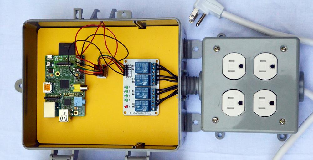
The relay board connects to two pairs of power outlets just like the ones in your wall, which you’ll use to plug in your light strands.
Connect the Hardware
While you could build your own separate relay controllers, plenty of vendors sell premade relay control cards with one, two, four, or eight relays on one card for less than it would cost to do it yourself. (That always hurts to say when you love to DIY, but sometimes it really is easier to just buy built.)
Then you just have to control the relays from the Pi. You’ll find both 5 V and 12 V relays for sale. Avoid the 12 V ones, which will require more level shifting as well as a second power supply. With a 5 V relay, all you’ll need to add is a 3.3-to-5 volt converter for the Raspberry Pi GPIO pins. Level converter boards are also readily available online from vendors like Adafruit and DX.com.
A level converter actually has several converters in one board: 5 V power, 3.3 V power, ground, and four signals going in and four signals going out. Converting the signal from 3.3 V out of the pins into the 5 V that the relay requires provides the necessary power to the relay while grounding the signal so it doesn’t fry the Raspberry Pi.
Do not use the 5 V power from the Raspberry Pi to power the relays. You could burn out your Pi.
Connect four differently colored male/female jumper wires from the following GPIO to the level converter board’s channels:
- Pin 23 to Channel 1
- Pin 22 to Channel 2
- Pin 27 to Channel 3
- Pin 17 to Channel 4
Next, connect the level converter to the relay board’s signal pins on VCC (5 V), each of the four channels, and ground (GND). (It may also have markings for voltage (V) and ground (G).
Opto-isolated relay boards might work without the level converter board.
Now, you’ll need to connect the relays to the outlets. Looking at the outlets, you will see that the screws on one side are brass, and the screws on the other side are silver. The brass side is the “hot” side that is controlled by the relay, while the silver side is the return. Start by breaking the tabs that tie the top and bottom outlets together on the brass side, so you can control the top and bottom outlets independently.
This is a potentially dangerous project! Keep the 120 V power at the relay far away from all low-voltage wiring on the Raspberry Pi. You could be seriously electrocuted by what otherwise seems like a simple short. Note that you might need to consult local/regional building codes on construction and installation of your finished project.
Next, connect a 16-gauge white copper wire to one of the silver screws (top or bottom, it does not matter) on each of the two outlets, and connect these two white wires to the white wire of a grounded power cord. You can purchase a three-wire grounded power cord at your local home improvement store—we simply pilfered one from a spare power strip.
Now it is time to run a wire to the relays. If you look carefully at the relays, you will see either two connectors per relay or three connectors per relay, depending on your specific version. If you have three wires, one is usually labeled NO (for Normally Open, which means it is off when not energized), another is labeled NC (for Normally Closed, which means it is on when not energized), and the third wire is the common.
You want to use the common wire and the Normally Open one. If you have only two connectors for each relay, you don’t need to worry about this. As long as you use the common side, it really doesn’t matter if you mix up the Normally Open and Normally Closed relay output as you can either change it later, or simply reverse the relay logic by boolean inverting the GPIO.output second parameter.
Run a 16-gauge black copper wire to the common of each relay and tie them all together to the black wire of the power cord. Run another 16-gauge black copper wire from the Normally Open (or only remaining connector if only two per relay) to each of the brass screws on the outlets. You can use a metallic silver marker on the ends of each of the black wires to indicate the channel number (1–4), so it will be easy to run it to the correct outlet. Be sure to label the outlets so you later remember which one is controlled by each channel.
Run a ground wire from the ground screw on each outlet (usually green) to the ground wire of the power plug. Check your wiring to make sure it is correct with no loose or frayed wires. Once you are sure everything looks good, screw the outlet into the box and screw on the outlet box cover. If you are using this for control of outdoor lighting, you should place the setup box in an area out of the elements, such as in a garage, under a porch, or even inside the house, and then run the wires to each of the outlets.
Install the Software
First, install the GPIO control library and Python tools. Pidora includes python-rpi.gpio by default, but you’ll need to install python-devel manually:
$su -c'yum install python-devel'
On Raspbian, you’ll need to install both python-rpi.gpio and python-devel:
$sudo apt-get install python-dev$sudo apt-get install python-rpi.gpio
Then add the following code (which you can also download from this book’s GitHub repository) to any directory:
#!/usr/bin/pythonimportRPi.GPIOasGPIOimporttimeDELAY=1## GPIO signals for the 4 relays## Note that there are enough GPIO signals to control multiple# 4-channel boards from the same RPi## Name the channels and note of the colors of your wires for reference#CH1=23# Channel 1 - BrownCH2=22# Channel 2 - OrangeCH3=27# Channel 3 - GreenCH4=17# Channel 4 - Yellow## Set up the four channels with GPIO signals as output#GPIO.setmode(GPIO.BCM)GPIO.setup(CH1,GPIO.OUT)GPIO.setup(CH2,GPIO.OUT)GPIO.setup(CH3,GPIO.OUT)GPIO.setup(CH4,GPIO.OUT)## The sequence for the relay controller - bit mask of each# of the 4 channels. This example first turns each of the# channels off, then cycles through each one, one at a time,# and then repeats the sequence again## Sequence table describes the order you want the lights to come on.#sequence=[0b0000,# All off0b0001,# Only channel 1 on0b0010,# Only channel 2 on0b0100,# Only channel 3 on0b1000]# Only channel 4 on## Start at the beginning of the sequence array#index=0## Run forever,,,#whileTrue:## Convert the integer sequence bitmask into the individual# channel controlsGPIO.output(CH1,((sequence[index]&1)==1))GPIO.output(CH2,((sequence[index]&2)==2))GPIO.output(CH3,((sequence[index]&4)==4))GPIO.output(CH4,((sequence[index]&8)==8))## Delay... make this as long a you want, or make it variable#time.sleep(DELAY)## Advance to the next pattern in the sequence#index=index+1if(index>=len(sequence)):index=0
Move this file (as root) to /usr/bin/lightsequences.py. You can save yourself some annoyance later by also setting it to be executable:
$ sudo chmod +x /usr/bin/lightsequences.pyYou probably want to make this Python script run automatically when your Raspberry Pi boots up. The way to do this is different between Pidora and Raspbian.
For Raspbian, you simply need to invoke this script from /etc/rc.local. Open that file with a text editor (as root), and add this line directly above the line that says exit 0:
python /usr/bin/lightsequences.py &
The use of the & command at the end of the line tells the Python script to run in the background. This is important, because otherwise, rc.local would wait for it to finish before proceeding. Since this script runs in an infinite loop, it would never proceed, and your boot process would sit there waiting.
Pidora uses a different boot software (systemd), which does not use the rc.local concept. As a result, you will need to create a new systemd service file for the Python script. Copy this file (also in the book’s GitHub repository) to /usr/lib/systemd/system/lightsequences.service (as root):
[Unit]Description=Christmas Light Sequence Loop[Service]Type=simpleExecStart=/usr/bin/python /usr/bin/lightsequences.py[Install]WantedBy=multi-user.target
Then, you can start it immediately by running:
$su -c'systemctl start lightsequences.service'
To make this service start on each boot, run:
$su -c'systemctl enable lightsequences.service'
From here, you have many options to expand and customize your light display. Having Ethernet included means you could add a web-based interface to start and stop the lights or to control them. Thanks to the audio-out jack, you can even use it as the sound source.
You could combine this hack with [Hack #49] to send the sound through a radio broadcast. With serial input coming in, you could use a MIDI sequence to control both lights and sound. With an attached camera, you could serve a picture of your changing display to the Web. And thanks to the Raspberry Pi, that’s all readily available in one package. Happy holidays!
—Rodney Radford
Get Raspberry Pi Hacks now with the O’Reilly learning platform.
O’Reilly members experience books, live events, courses curated by job role, and more from O’Reilly and nearly 200 top publishers.

