Chapter 28. Content Switch Modules in Action
Figure 28-1 shows a simple load-balanced network that I've built to illustrate some common configuration tasks. The load balancer in use is a pair of Cisco Content Switch Modules in a pair of Cisco 6509 switches. The virtual servers reside on the 10.5.5.0/24 network, while the real servers reside on the 10.10.10.0/24 network.
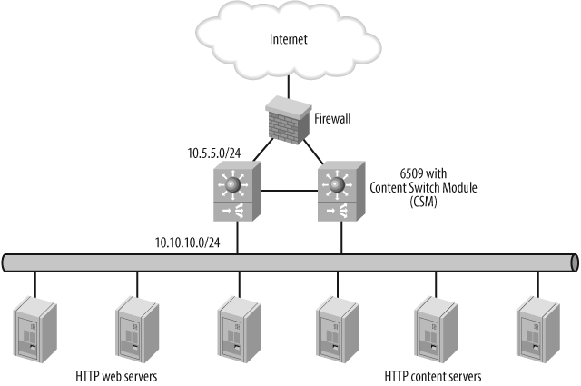
Figure 28-1. Simple load-balanced network
Here is the configuration for the CSM in the first switch. The second switch will
inherit the configuration from the first through the ft
group command, and the alt configurations in
the VLAN IP addresses. This configuration was created in the previous chapter, so it should
all be familiar:
module ContentSwitchingModule 8 ft group 1 vlan 88 priority 15 preempt ! vlan 3 client ip address 10.5.5.3 255.255.255.0 alt 10.5.5.4 255.255.255.0 gateway 10.5.5.1 ! vlan 4 server ip address 10.10.10.1 255.255.0.0 alt 10.10.10.2 255.255.0.0 alias 10.10.10.1 ! real CONTENT-00 address 10.10.10.16 inservice real CONTENT-01 address 10.10.10.17 inservice real CONTENT-02 address 10.10.10.18 inservice real CONTENT-03 address 10.10.10.19 inservice real CONTENT-04 address 10.10.10.20 inservice ! real HTTP-00 address 10.10.10.32 no inservice real HTTP-01 address 10.10.10.33 no inservice real HTTP-02 address 10.10.10.34 inservice real HTTP-03 address 10.10.10.35 inservice real HTTP-04 address 10.10.10.36 ...
Get Network Warrior now with the O’Reilly learning platform.
O’Reilly members experience books, live events, courses curated by job role, and more from O’Reilly and nearly 200 top publishers.

