Virtual LANs, or VLANs, are virtual separations within a switch that provide distinct logical LANs that each behave as if they were configured on a separate physical switch. Before the introduction of VLANs, one switch could serve only one LAN. VLANs enabled a single switch to serve multiple LANs. Assuming no vulnerabilities exist in the switch's operating system, there is no way for a frame that originates on one VLAN to make its way to another.
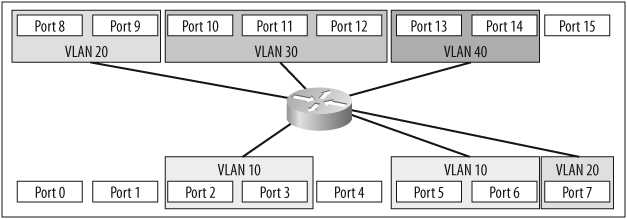
Figure 4-1 shows a switch with multiple VLANs. The VLANs have been numbered 10, 20, 30, and 40. In general, VLANs can be named or numbered; Cisco's implementation uses numbers to identify VLANs by default. The default VLAN is numbered 1. If you plug a number of devices into a switch without assigning its ports to specific VLANs, all the devices will be in VLAN 1.
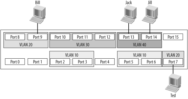
Frames cannot leave the VLANs from which they originate. This means that in the example configuration, Jack can communicate with Jill, and Bill can communicate with Ted, but Bill and Ted cannot communicate with Jack or Jill in any way.
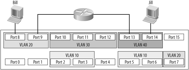
For a packet on a layer-2 switch to cross from one VLAN to another, an outside router must be attached to each of the VLANs to be routed. Figure 4-2 shows an external router connecting VLAN 20 with VLAN 40. Assuming a proper configuration on the router, Bill will now be able to communicate with Jill, but neither workstation will show any indication that they reside on the same physical switch.
When expanding a network using VLANs, the same limitations apply. If you connect another switch to a port that is configured for VLAN 20, the new switch will be able to forward frames only to or from VLAN 20. If you wanted to connect two switches, each containing four VLANs, you would need four links between the switches: one for each VLAN. A solution to this problem is to deploy trunks between switches. Trunks are links that carry frames for more than one VLAN.
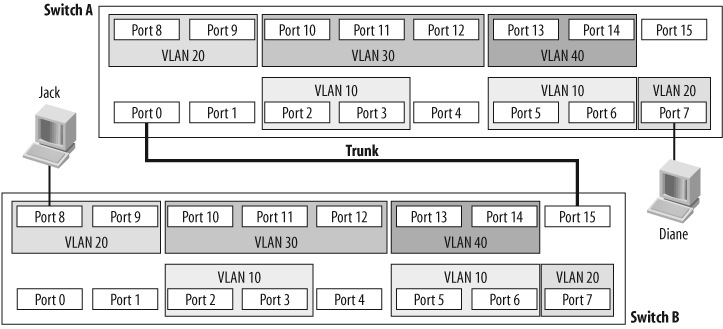
Figure 4-3 shows two switches connected with a trunk. Jack is connected to VLAN 20 on Switch B, and Diane is connected to VLAN 20 on Switch A. Because there is a trunk connecting these two switches together, assuming the trunk is allowed to carry traffic for all configured VLANs, Jack will be able to communicate with Diane. Notice that the ports to which the trunk is connected are not assigned VLANs. These ports are trunk ports, and as such, do not belong to a single VLAN.
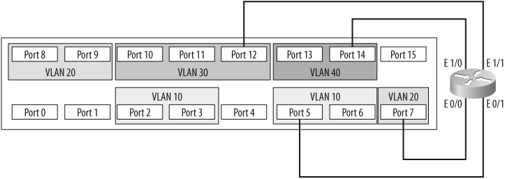
Trunks also allow another possibility with switches. Figure 4-2 showed how two VLANs can be connected with a router, as if the VLANs were separate physical networks. Imagine if you wanted to route between all of the VLANs on the switch. How would you go about such a design? Traditionally, the answer would be to provide a single connection from the router to each of the networks to be routed. On this switch, each of the networks is a VLAN, so you'd need a physical connection between the router and each VLAN.
As you can see in Figure 4-4, with this setup, four interfaces are being used both on the switch and on the router. Smaller routers rarely have four Ethernet interfaces, though, and Ethernet interfaces on routers can be costly. Additionally, switches are bought with a certain port density in mind. In this configuration, a quarter of the entire switch has been used up just for routing between VLANs.
Another way to route between VLANs is commonly known as the router on a stick configuration. Instead of running a link from each VLAN to a router interface, you can run a single trunk from the switch to the router. All the VLANs will then pass over a single link, as shown in Figure 4-5.

Deploying a router on a stick saves a lot of interfaces on both the switch and the router. The downside is that the trunk is only one link, and the total bandwidth available on that link is only 10 Mbps. In contrast, when each VLAN has its own link, each VLAN has 10 Mbps to itself. Also, don't forget that the router is passing traffic between VLANs, so chances are each frame will be seen twice on the same linkâonce to get to the router, and once to get back to the destination VLAN.
Using a switch with a router is not very common anymore because most vendors offer switches with layer-3 functionality built-in. Figure 4-6 shows conceptually how the same design would be accomplished with a layer-3 switch. Because the switch contains the router, no external links are required. With a layer-3 switch, every port can be dedicated to devices or trunks to other switches.
Get Network Warrior now with the O’Reilly learning platform.
O’Reilly members experience books, live events, courses curated by job role, and more from O’Reilly and nearly 200 top publishers.

