Chapter 4. LED Matrix Light Show
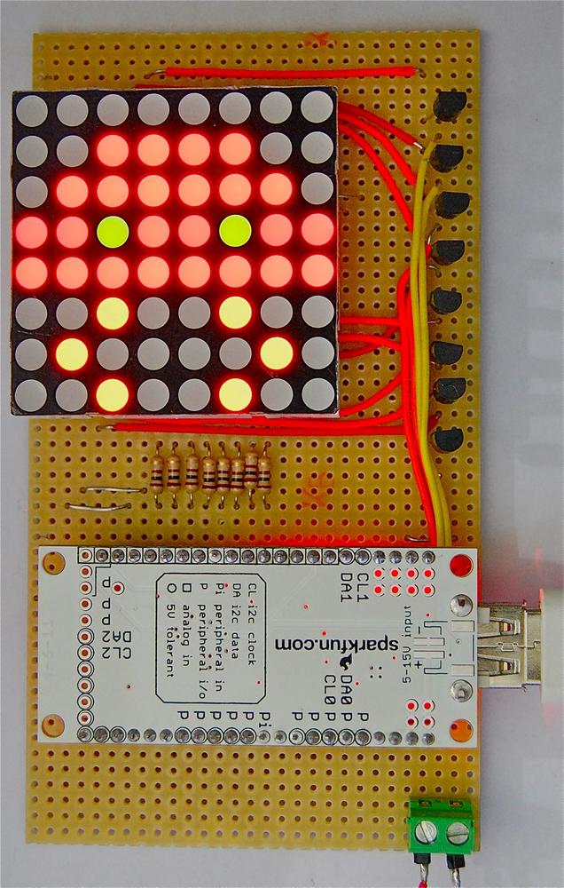
This chapter uses a multicolor LED matrix to make a fun charger for your Android phone (Figure 4-1). In this particular case, “fun” takes the form of a marching Space Invader animation—and if that isn’t fun, I don’t know what is!
The project has a variety of different modes: it can just display a static image, or it can display an animation, or it can make use of the phone’s microphone to provide a spectrum type display. If you start your music player on the phone before you start the IOIO Matrix app, it will respond to the sounds coming from your phone.
This is the only project in the book that will not work using a Bluetooth adaptor rather than a USB cable. This is because Bluetooth simply isn’t fast enough to send the commands to the pins to refresh the display.
The Design
In this design, the IOIO board uses 24 of its pins to control the LED Matrix. It requires 24 pins because the LED Matrix is arranged as a grid of LEDs. Each cell in the matrix actually has two LEDs in it, one red and one green. This is used to set the color of any individual cell to red, green or—if both LEDs are lit at the same time—orange.
Schematic
Figure 4-2 shows the schematic diagram for the project.
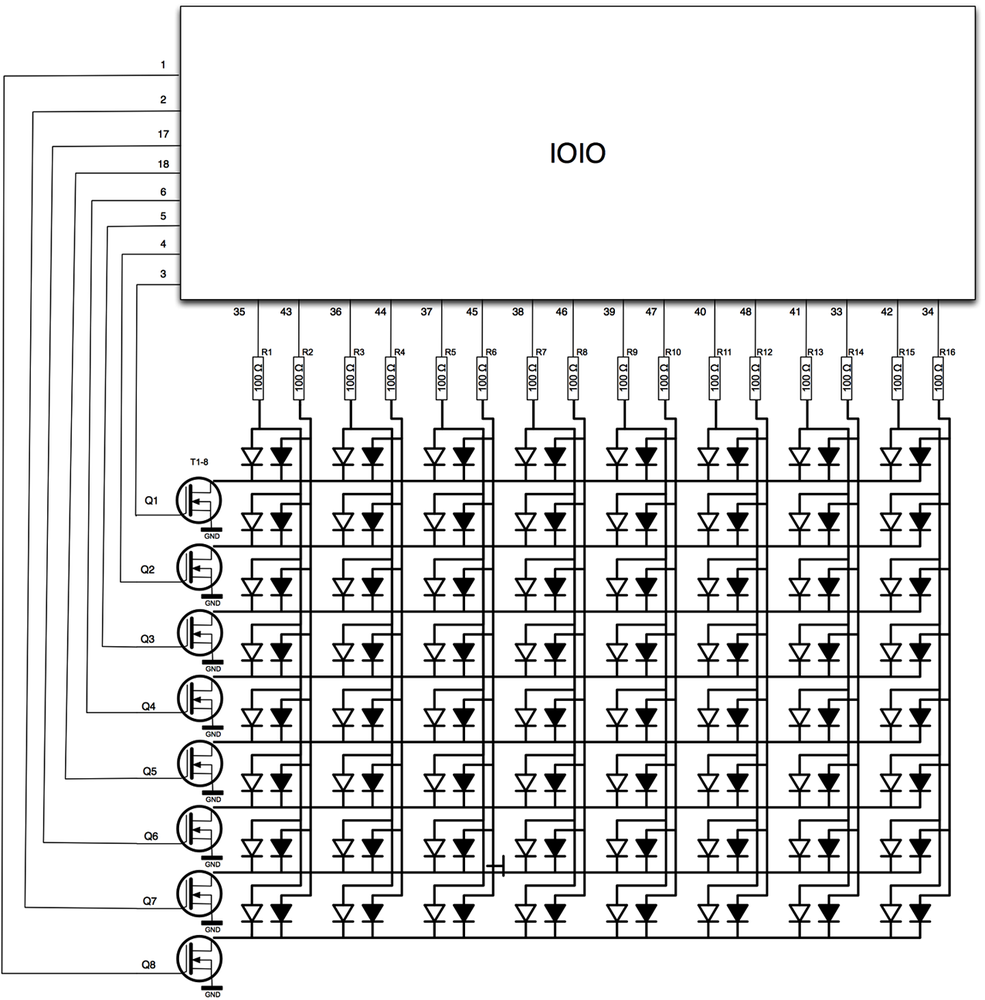
The anodes of the LEDs are each driven by a GPIO pin on the IOIO. Each has a series resistor to limit the current to the LED.
Because 8 LEDs share each common cathode connection to ground, there would be too much current flowing for a GPIO pin to sink, so a MOSFET transistor is used to switch each column in turn. The gate of each MOSFET is connected directly to a GPIO pin.
Wiring Diagram
The project is built on a piece of stripboard. Stripboard is a kind of prototyping board, with parallel tracks of copper running on one side of the board. Component leads are pushed through from the top and soldered to the copper track below.
On one side of the stripboard is a set of header pins designed to accept the IOIO board with its header sockets attached. The IOIO board will be fitted upside down onto the headers. The other side contains header sockets into which the LED Matrix is fitted.
A screw terminal for Vin and GND is used to simplify the process of providing power to the project.
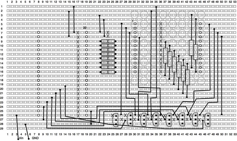
Figure 4-3 shows the stripboard layout for the project.
Construction
You will need the following parts to construct this project.
| Quantity | Description | SparkFun SKU | Farnell code | Newark code |
1 | 8 x 8 Dual-color LED Matrix | COM-00682 | ||
8 | 2N7000 MOSFETS | 9845178 | 89K1814 | |
16 | 100Ω 0.5W metal film resistor | 9339760 | 58K3723 | |
2 | SIL Header socket strip | PRT-00115 | 1217038 | 52K3454 |
2 | SIL header pins | PRT-00116 | 1097954 | 93K5128 |
1 | Screw terminal block | PRT-08084 | 1641932 | 19P1412 |
1 | Stripboard 29 strips each of 53 holes | 1201473 | 96K6336 |
Step 1. Prepare the Stripboard
The first step is to cut the stripboard to the correct size. The best way to do this is to use a craft knife to heavily score a line through the holes on the line below the last strip or column you need, and then break the board over the edge of your work desk. Be careful doing this, as it can leave sharp edges.
You then need to break the track in the positions indicated by an X in Figure 4-3. I find it useful to mark rows and columns 10, 20, 30, etc., on the top of the board to find the right position for the break and then push a wire through to find the position on the track side of the board. I use a drill bit, twisted between my fingers to remove the copper.
Figure 4-4 shows the copper side of the board, with all the breaks drilled.
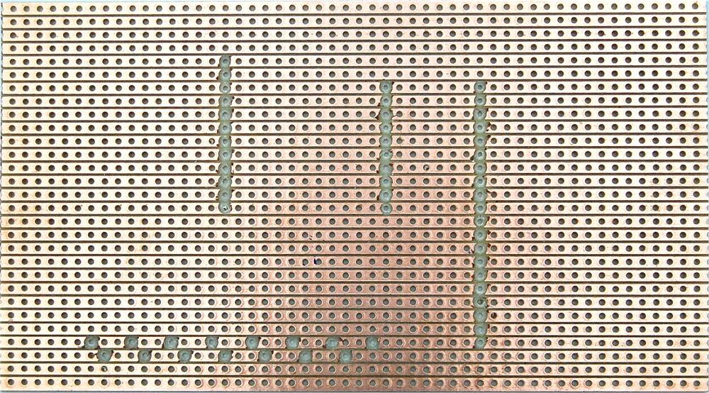
You may find it easier to work from Figure 4-4 than Figure 4-3. When you have made all the breaks, go back and inspect every one carefully to make sure that there is no trace of copper remaining, as this could cause a short and potentially destroy your IOIO. If in doubt, you can also use your multimeter on continuity mode, to make sure the break is clean.
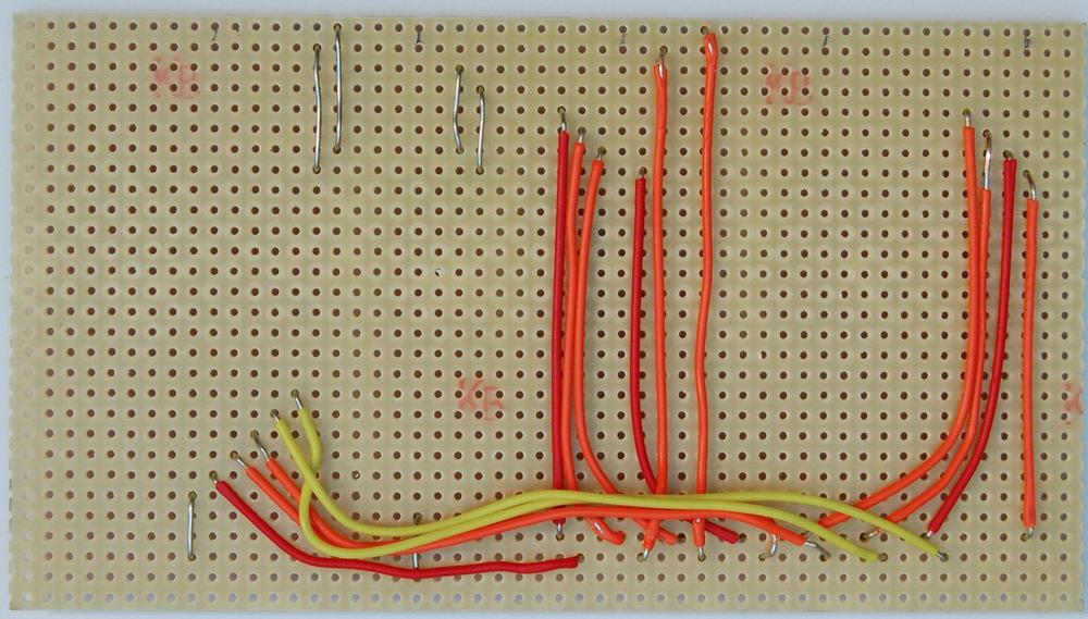
Step 2. Fit the Link Wires
The copper tracks on the bottom will anchor our components and make some of the connections. However, there are a lot more connections to be made with linking wires. The longer leads should be made using insulated solid core wire, and the shorter connections can just be bare wire.
Using Figure 4-3 as a reference, solder link wires into place. Note that this is not a quick job. You should put aside an hour to do this, because there are a lot of links to put in place.
Do not be tempted to solder the header pins in place first. Although this would make it much easier to work out where the link wires need to go, it makes it much harder to solder the links themselves into place, as they will just fall out when you turn the board upside-down to solder it.
When all the links are in place, you should have a board that looks like Figure 4-5.
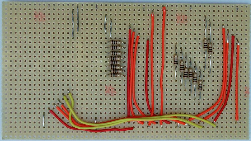
Step 3. Fit the Resistors
The next step is to fit the next lowest parts, which are the resistors. Again, using Figure 4-3 as a reference, solder them into place. When all the resistors are in position, your board should look like Figure 4-6.
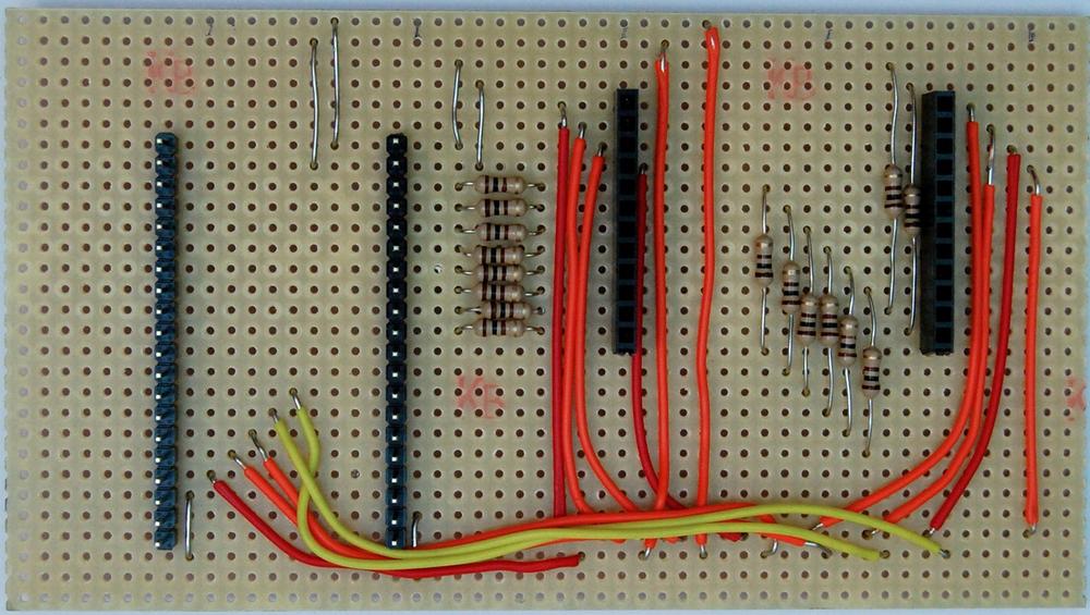
Step 4. Fit the Headers
You can make it easier to fit the header plugs into the IOIO and the sockets into the LED Matrix by fitting the components into the headers before putting them in the right position on the board. Double-check that the placement is correct, as it will be hard to unsolder them once they are in position.
If the header strips are not the right lengths, you will need to cut them to the right number of connections using a craft knife. When cutting the sockets, this will usually mean sacrificing one of the socket connections, so cut through the socket after the number you need, rather than try and cut between sockets.
Once the sockets are in place, your board should look like Figure 4-7.
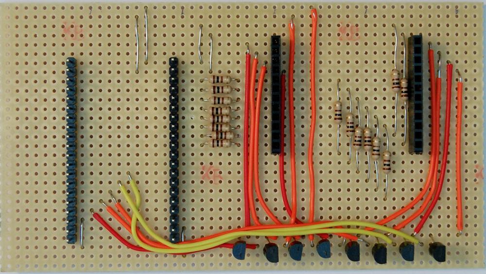
Step 5. Fit the MOSFETs
The last components to be added to the board are the MOSFET transistors. Be careful to ensure that they are the right way around, and solder them into place, raised about 1/4 inch above the surface of the board.
Figure 4-8 shows the board with the MOSFETs in place.
Step 6. Fit the Power Terminal and IOIO
That’s pretty much all the hardware. It just remains to solder the screw terminal for the power into place, and then fit the LED Matrix and IOIO (Figure 4-9).
Solder the screw terminal block into place first and mark the upper connection with a + to reduce the chance of applying the supply voltage reversed.
The LED Matrix has little cutouts and pegs to allow bigger displays to be made by joining more than one of them together. The correct orientation for the cutouts is at the bottom and left of the board.
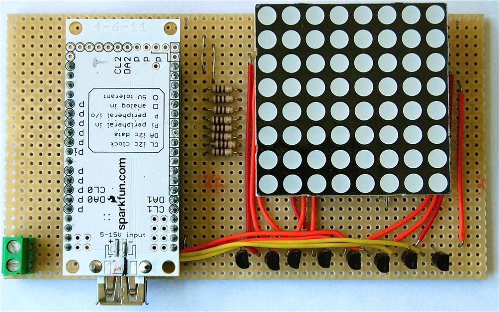
Figure 4-9 shows the board fully assembled and ready to go.
Software
They key to this project is being able to refresh the screen fast
enough. This is all wrapped up in the chain of methods in
MainActivity.java that start with refreshMatrix:
private void refreshMatrix() throws ConnectionLostException {
  for (int col = 0; col < 8; col++) {
    clearPreviousColumn(col);
    displayColumn(col);
    delay(3);
  }
}
This iterates for each column, clearing its previous settings, displaying the new column, and then sleeping for 3 milliseconds:
private void clearPreviousColumn(int col) throws ConnectionLostException {
  int columnToClear = col - 1;
  if (columnToClear == -1)
  {
    columnToClear = 7;
  }
  cc[columnToClear].write(false);
  for (int row = 0; row < 8; row++) {
    r[row].write(false);
    g[row].write(false);
  }
}
Clearing the previous column is a matter of finding the column before the current one, including wrapping round. We then turn off the common cathode on the LED matrix for the column in question and then turn off all the red and green anodes for all 8 rows:
private void displayColumn(int col) throws ConnectionLostException {
  cc[col].write(true);
  for (int row = 0; row < 8; row++) {
    r[row].write((display_[col][row] & 1) > 0);
    g[row].write((display_[col][row] & 2) > 0);
  }
}
Displaying the new column involves turning on the appropriate common
cathode of the LED matrix, and then setting the red and green anodes
according to the current column of the 2D array of colors held in the
member variable display_, which looks
something like this:
private int[][] testPattern1_ = {
    {1,1,1,1,1,1,1,1},
    {1,2,2,2,2,2,2,2},
    {1,2,3,3,3,3,3,3},
    {1,2,3,1,1,1,1,1},
    {1,2,3,1,2,2,2,2},
    {1,2,3,1,2,3,3,3},
    {1,2,3,1,2,3,1,1},
    {1,2,3,1,2,3,1,2}
};
The number 0 means both LEDs are off; 1, red LED; 2, green LED; and 3, both LEDs on (orange).
Everything else in this app, including the animation, is just a
matter of assigning display_ to a
different 2D array every half second.
The frames of the animation are defined in a separate class file,
which is also responsible for providing a value (frameDelay) for the time between frames in
milliseconds:
package com.ioiobook.matrix;

public class TestAnimation {

        public final static int frameDelay = 500;

        public final static int[][][] animation = {
                { //1
                        {0,0,1,1,1,1,0,0},
                        {0,1,1,1,1,1,1,0},
                        {1,1,2,1,1,2,1,1},
                        {1,1,1,1,1,1,1,1},
                        {0,0,3,0,0,3,0,0},
                        {0,0,3,0,0,3,0,0},
                        {0,0,3,0,0,3,0,0},
                        {0,0,0,0,0,0,0,0}
                },
                { //2
                        {0,0,0,0,0,0,0,0},
                        {0,0,1,1,1,1,0,0},
                        {0,1,1,1,1,1,1,0},
                        {1,1,2,1,1,2,1,1},
                        {1,1,1,1,1,1,1,1},
                        {0,0,3,0,0,3,0,0},
                        {0,3,0,0,0,0,3,0},
                        {0,0,3,0,0,3,0,0}
                },
The spectrum display makes use of a third-party open source library,
wrapped up in a class (SpectrumDrawer.java). This is instantiated with
a display to draw on:
public class SpectrumDrawer {

    private float gain_ = 1000000.0f;
    private int[][] displayArray_;
    private Window win_;
    private FFTTransformer spectrumAnalyser_;
    private int historyIndex_;
    private float[] average_;
    private float[][] histories_;

    // 128 values in average_ we just want 8 - Fn = n * Fs / N
    // where Fn is freq at data point n, Fs is the sample freq
    // and N is the buffer size
    private final int[] frequencies_ = { 2, 4, 6, 10, 15, 25, 55, 80 };
    private final int[] colors_ = { 2, 2, 3, 3, 3, 1, 1, 1 };

    public SpectrumDrawer(int[][] display) {
        displayArray_ = display;
        win_ = new Window(MainActivity.AUDIO_BUFFER_SIZE,
                Window.Function.BLACKMAN_HARRIS);
        spectrumAnalyser_ = new
FFTTransformer(MainActivity.AUDIO_BUFFER_SIZE, win_);        average_ = new float[MainActivity.AUDIO_BUFFER_SIZE / 2];
        histories_ = new float[MainActivity.AUDIO_BUFFER_SIZE / 2][MainActivity.AUDIO_BUFFER_SIZE / 2];
    }

    public void calculateSpectrum(short[] buffer) {
        // apply FFT to the buffer to get the spectrum,
        // but we only have 8 columns
        // so sum into 8 bands
        spectrumAnalyser_.setInput(buffer, 0, MainActivity.AUDIO_BUFFER_SIZE);
        spectrumAnalyser_.transform();
        historyIndex_ = spectrumAnalyser_.getResults(average_, histories_,
                historyIndex_);

        for (int c = 0; c < 8; c++) {
            int resultIndex = frequencies_[c];
            // Do we need to log this?
            int power = (int) (Math.log(average_[resultIndex] * gain_));
            Log.d("SRM", "" + power);
            if (power > 7)
                power = 7;
            for (int r = 0; r < 8; r++) {
                if (power > r) {
                    displayArray_[7 - r][c] = colors_[r];
                } else {
                    displayArray_[7 - r][c] = 0;
                }
            }
        }
    }
}
When the calculateSpectrum method
is called, a Fast Fourier Transform (FFT) is applied to a sample of the
audio from the phone’s microphone.
A FFT is used in this case to take a sample of an audio file and find the relative sizes of each of the frequencies that make up the sound. This produces an array of the power of a range of frequencies. We can then pick off frequencies from this and use them to set the colors of the matrix display.
The histories_ array is required
by the third-party library to provide averaging of the FFT results.
For each column, we light a number of LEDs in the rows equal to the
power. The actual color of each of the lit LEDs is determined by the
colors_ array.
To feed the SpectrumDrawer with
new data, a separate thread is started in the onCreate method of the MainActivity class:
AudioReader.Listener listener = new AudioReader.Listener()
{

        @Override
        public void onReadComplete(short[] buffer) {
                spectrumDrawer_.calculateSpectrum(buffer);
        }

        @Override
        public void onReadError(int error) {

        }

};
audioReader_ = new AudioReader();
audioReader_.startReader(F, AUDIO_BUFFER_SIZE, listener);
The thread is encapsulated in the AudioReader class. This class is provided in the
org.hermit library.
Conclusion
This is quite a challenging project, both for the builder and the IOIO that has to keep updating the outputs to keep the display alive.
The app is intended as a starting point for your own experiments. There are many ways that it could be improved, including a file format for the animations to that they can be loaded and a optimization of the display mechanism to reduce flicker.
In the final chapter in this book, we are going to get more physical and make a little Bluetooth-controlled rover.
Get Making Android Accessories with IOIO now with the O’Reilly learning platform.
O’Reilly members experience books, live events, courses curated by job role, and more from O’Reilly and nearly 200 top publishers.

