Full-duplex is an optional mode of operation allowing simultaneous communication between a pair of stations. The link between the stations must use a point-to-point media segment, such as twisted-pair or fiber optic media, to provide independent transmit and receive data paths. With full-duplex mode enabled, both stations can simultaneously transmit and receive, which doubles the aggregate capacity of the link. For example, a half-duplex Fast Ethernet twisted-pair segment provides a maximum of 100 Mbps of bandwidth. When operated in full-duplex, the same 100BASE-TX twisted-pair segment can provide a total bandwidth of 200 Mbps.
Another major advantage of full-duplex operation is that the maximum segment length is no longer limited by the timing requirements of shared channel half-duplex Ethernet. In full-duplex mode, the only limits are those set by the signal-carrying capabilities of the media segment. This is especially useful for fiber optic segments.
The optional full-duplex mode is specified in the 802.3x supplement to the standard, which formally describes the methods used for full-duplex operation. This supplement was approved for adoption into the IEEE 802.3 standard in March 1997. The 802.3x supplement also describes an optional set of mechanisms used for flow control over full-duplex links. The mechanisms used to establish flow control are called MAC Control and PAUSE. First we’ll describe how full-duplex mode works, and then we’ll show how the MAC Control and PAUSE mechanisms can be used to provide flow control over a full-duplex link.
The following requirements, as stated in the 802.3x standard, must be met for full-duplex operation:
The media system must have independent transmit and receive data paths that can operate simultaneously. Such data paths are typically found on twisted-pair and fiber optic links.
There are exactly two stations connected with a full-duplex point-to-point link. Since there is no contention for use of a shared medium, the multiple access algorithms (i.e., Carrier Sense with Multiple Access and Collision Detect, or CSMA/CD) are unnecessary.
Both stations on the LAN are capable of, and have been configured to use, the full-duplex mode of operation. This means that both Ethernet interfaces must have the capability to simultaneously transmit and receive frames.
The original mode of Ethernet operation is half-duplex, based on CSMA/CD. The operation of CSMA/CD is described in detail in Chapter 3. In the CSMA/CD-based half-duplex mode of operation, only one station can transmit at any given time; other stations must defer until that transmission is complete.
Warning
Ethernet repeaters as defined in the IEEE 802.3 standard are not stations and cannot be operated in full-duplex mode. Ethernet repeaters simply pass Ethernet signals between attached segments, and a repeater can only operate in half-duplex mode.
Beware of confusing terms that you may find in advertising or network trade journals, such as “full-duplex repeater.” Vendors have created devices which they call "buffered repeaters,” “buffered distributors,” and “full-duplex repeaters,” but these are not true repeaters. The operation and configuration of these devices is not described in the Ethernet standard and system configuration guidelines. Instead, these devices typically operate as switching hubs. Switching hubs are described in Chapter 18.
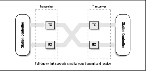
Figure 4.1 shows two stations simultaneously sending and receiving over a full-duplex link segment. The segment provides independent data paths so that both stations can be active without interfering with one another’s transmissions. To provide full-duplex operation, both the station interface (controller ) and the transceiver at each station must support and be configured for full-duplex operation.
When sending a frame in full-duplex mode, the station ignores carrier sense and does not defer to traffic being received on the channel. However, the station still waits for an interframe gap period between frame transmissions as Ethernet interfaces are designed to expect an interframe gap between successive frames. Providing the interframe gap ensures that the interfaces at each end of the link can keep up with the full frame rate of the link. In full-duplex mode, the stations at each end of the link ignore any collision detect signals that come from the transceiver. If the transceiver has a collision detect light, then placing the transceiver in full-duplex mode means that the significance of the collision detect light is undefined, and the light should be ignored.
The CSMA/CD algorithm used on shared half-duplex Ethernet channels is not used on a link operating in full-duplex mode. A station on a full-duplex link sends whenever it likes, ignoring carrier sense (CS). There is no multiple access (MA) since there is only one station at each end of the link and the Ethernet channel between them is not the subject of access contention by multiple stations. Since there is no access contention, there will be no collisions either, so the station at each end of the link is free to ignore collision detect (CD).
While full-duplex operation has the potential to double the bandwidth of an Ethernet link segment, it usually won’t result in a large increase in performance on a link that connects to a user’s computer. That’s because most network protocols are designed to send data and then wait for an acknowledgment. This leads to asymmetric data patterns, in which most of the data is sent in one direction, and smaller amounts of data (in the form of acknowledgments) return in the other direction.
On the other hand, full-duplex links between switching hubs in a network backbone system will typically carry multiple conversations between many computers. Therefore, the aggregated traffic on backbone channels will be more symmetric, with both the transmit and receive channels seeing roughly the same amount of traffic. For that reason, the largest benefit of a full-duplex bandwidth increase is usually seen in backbone links.
Nonetheless, configuring a link to a user’s computer for full-duplex operation can still be useful. For example, if it’s a modern computer capable of placing a heavy load on an Ethernet channel, it might encounter the Ethernet capture effect described in Chapter 3. Configuring full-duplex mode shuts off the CSMA/CD algorithm and avoids any problems with capture effect.
It is essential that both ends of a link operating in full-duplex mode are configured correctly, or the link will have serious data errors. To ensure correct configuration, the standard recommends that Ethernet Auto-Negotiation (see Chapter 5) be used whenever possible to automatically configure full-duplex mode.
However, using Auto-Negotiation to configure full-duplex operation on a link may not be as simple as it sounds. For one thing, support for Auto-Negotiation is optional for most Ethernet media systems, in which case the vendor is not required to provide Auto-Negotiation capability. Furthermore, Auto-Negotiation was originally developed for twisted-pair Ethernet devices only, and thus it is not supported on all Ethernet media types. The 10 Mbps and 100 Mbps fiber optic media systems do not support the Auto-Negotiation standard, while Gigabit Ethernet fiber optic systems have their own auto-configuration scheme. Therefore, you may find that you have to manually configure full-duplex support on the station at each end of the link.
On a manually configured link, it is essential that both ends of the link be properly configured for full-duplex operation. If only one end of the link is in full-duplex mode, and the other is in half-duplex mode, then the half-duplex end of the link will lose frames due to errors, such as late collisions. Data will still flow across the link, but as the full-duplex end will be sending data whenever it pleases, it will not be obeying the same CSMA/CD rules as the half-duplex end. Because the misconfigured link will still support the flow of data (despite the errors), it is possible that this problem may not be detected right away. Therefore, you need to be aware that this condition can occur, and make absolutely sure that both ends of a manually configured link are set for the same mode of operation.
At each end of the link, you must also ensure that both the Ethernet interface and the transceiver are configured for full-duplex operation. This can be difficult in some cases, since the 10 Mbps Attachment Unit Interface (AUI) used between an Ethernet interface and an external transceiver was designed before full-duplex mode was developed and does not support automatic full-duplex configuration.[1]
For this reason, the standard recommends that only 10 Mbps Ethernet interfaces with built-in transceivers be used for full-duplex segments. That’s because the 15-pin AUI connector used to connect to external transceivers does not provide any way for the Ethernet interface in the station to discover the capabilities of the external transceiver and to correctly set the mode of the transceiver. As a result, when using an external transceiver with a 15-pin connection, you could end up with a transceiver in half-duplex mode connected to an interface in full-duplex mode. On the other hand, the newer 40-pin Medium Independent Interface (MII), which supports both 10 and 100 Mbps Ethernet systems, makes it possible for the interface to detect and set the operational mode of an external transceiver.
If an external transceiver is used, then it is essential that the mode of operation of the Ethernet interface and the transceiver at a given station match. There can be problems if an Ethernet interface in full-duplex mode is connected to a transceiver in half-duplex mode, or if the station interfaces are not in the same mode. The standard notes that this sort of confusion
... can lead to severe network performance degradation, increased collisions, late collisions, CRC errors, and undetected data corruption.[2]
Table 4.1 provides a complete list of Ethernet media systems, and shows which ones can support the full-duplex mode of operation.
Table 4.1. Full-Duplex Media Support
|
Media System |
Cable Type |
Full-Duplex Support? |
|---|---|---|
|
10BASE5 |
50 ohm thick coaxial cable |
No |
|
10BASE2 |
50 ohm thin coaxial cable |
No |
|
10BASE-T |
2-pair Category 3/4/5 twisted-pair |
Yes[3] |
|
10BASE-FL |
2 multimode optical fibers (MMF) |
Yes |
|
10BASE-FB[4] |
2 multimode optical fibers |
No |
|
10BASE-FP[5] |
2 multimode optical fibers |
No |
|
10BROAD36 |
75 ohm coaxial cable |
No |
|
100BASE-TX |
2-pair Category 5 twisted-pair |
Yes |
|
100BASE-FX |
2 multimode optical fibers |
Yes |
|
100BASE-T4 |
4-pair Category 3 twisted-pair |
No |
|
100BASE-T2 |
2-pair Category 3/4/5 twisted-pair |
Yes |
|
1000BASE-SX |
2 multimode optical fibers |
Yes |
|
1000BASE-LX |
2 MMF or single-mode optical fibers |
Yes |
|
1000BASE-CX |
2-pair shielded twisted-pair |
Yes |
|
1000BASE-T |
4-pair Category 5 twisted-pair |
Yes |
[3] Although the media system supports full-duplex mode, an external transceiver with a 15-pin AUI interface must be specifically configured for full-duplex operation. More modern external transceivers with 40-pin MII interfaces are automatically configured by the station interface. [4] The 10BASE-FB, 10BROAD36 and 100BASE-T4 equipment was sold only by a few vendors, and these media systems are not widely used. [5] The 10BASE-FP and 100BASE-T2 media systems were never developed by any vendor, and are not deployed. | ||
When a segment is operating in full-duplex mode, the CSMA/CD-based MAC is shut off. As a result, cable length limits imposed by the round-trip timing constraints of the CSMA/CD algorithm no longer exist. Since there is no round-trip timing limit, the only limit on the length of the cabling is the one imposed by the signal transmission characteristics of the cable. For that reason, some full-duplex segments can be much longer than the same segments operated in half-duplex mode.
Twisted-pair segments are limited in distance due to the signal carrying characteristics of the cable, and cannot be extended in length when operated in full-duplex mode. A maximum cabling distance recommendation of 100 meters (328 feet) for unshielded twisted-pair cable is common to the 10BASE-T, 100BASE-TX and 1000BASE-T media systems. Due to the restricted signal carrying capability of twisted-pair cable, the maximum limit for a twisted-pair cable segment is the same whether the segment is operated in full-duplex or half-duplex mode.
Fiber optic segments, on the other hand, have very good signal carrying characteristics and are mostly limited in length by the timing constraints of half-duplex operation. For that reason, a full-duplex mode fiber optic segment can be considerably longer than the same segment type operating in half-duplex mode. As an example, a 100BASE-FX fiber optic segment using a typical multimode fiber optic cable is limited to segment lengths of 412 meters (1351.6 feet) in half-duplex mode. However, the same media system can reach as far as 2 km (6561.6 feet) when operated in full-duplex mode.
Single-mode fiber optic media can carry signals over longer distances than multi-mode fiber. Therefore, a full-duplex fiber link can be stretched considerably further if single mode fiber media is used. In the case of a 100BASE-FX link, single-mode fiber can provide link distances of 20 km or more. For full-duplex links, you need to consult the equipment vendor for specifications on the maximum length of the segment.
The rate of traffic on network backbones is always growing, and as a result backbone switches connected together with full-duplex links can be heavily loaded with traffic. A switching hub typically has a fixed set of resources, in the form of internal switching bandwidth and packet buffers, which it apportions to its switching ports. Resources like packet buffer memory are expensive, and many low-cost switches limit these resources. To keep these limited resources from being overwhelmed, a variety of non-standard flow control mechanisms were developed by switching hub vendors for use on half-duplex segments. These include the use of a short burst of carrier signal sent by the switching hub to cause stations on a half-duplex segment to stop sending data when the buffers on a switching port are full. These mechanisms are described in more detail in Chapter 18.
This sort of mechanism is based on the half-duplex mode of operation—it will not work on a full-duplex segment that is not using the CSMA/CD algorithm and ignores things like carrier. As a result, a switching hub connected to full-duplex segments needs a new mechanism to send a flow control message. To that end, an explicit flow control message is provided by the optional MAC Control and PAUSE specifications in the 802.3x Full-Duplex supplement.
The optional MAC Control portion of the 802.3x supplement provides a mechanism for real-time control and manipulation of the frame transmission and reception process in an Ethernet station. In normal Ethernet operation, the media access control (MAC) protocol defines how to go about transmitting and receiving frames. In the optional Ethernet flow control system, the MAC Control protocol provides mechanisms to control when Ethernet frames are sent.
When implemented, the MAC Control system provides a way for the station to receive a MAC Control frame and act upon it. The operation of the MAC Control system is transparent to the normal media access control functions in a station. MAC Control is not used for a non-real-time function like configuring interfaces, which is handled by network management mechanisms. Instead, MAC Control is designed to allow stations to interact in real time to control the flow of traffic. New functions beyond flow control may be added in the future.
MAC Control frames are identified with a type value of 0x8808 (hex). A station equipped with optional MAC Control receives all frames using the normal Ethernet MAC functions, and then passes the frames to the MAC Control software for interpretation. If the frame contains the hex value 0x8808 in the type field, then the MAC Control function reads the frame, looking for MAC Control operation codes carried in the data field. If the frame does not contain the 0x8808 value in the type field, then MAC Control takes no action, and the frame is passed along to the normal frame reception software on the station.
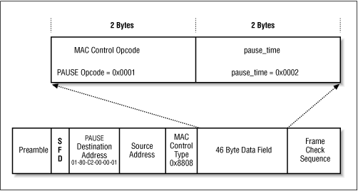
MAC Control frames contain operational codes (opcodes) in the data field of the frame. The frame size is fixed at the minimum frame size allowed in the standard, which is 46 bytes. The opcode is contained in the first two bytes of the data field. There is no reliable transport mechanism, so MAC Control must be able to deal with the fact that MAC Control frames may be lost, discarded, damaged, or delayed.
The PAUSE system of flow control on full-duplex link segments is defined in 802.3x and uses MAC Control frames to carry the PAUSE commands.[6] The MAC Control opcode for a PAUSE command is 0x0001 (hex). A station that receives a MAC Control frame with this opcode in the first two bytes of the data field knows that the control frame is being used to implement the PAUSE operation, for the purpose of providing flow control on a full-duplex link segment. Only stations configured for full-duplex operation may send PAUSE frames.
When a station equipped with MAC Control wishes to send a PAUSE command, it sends a PAUSE frame to the 48-bit destination multicast address of 01-80-C2-00-00-01. This particular multicast address has been reserved for use in PAUSE frames. The use of a well-known multicast address simplifies the flow control process by making it unnecessary for a station at one end of the link to discover and store the address of the station at the other end of the link.
Another advantage of using this multicast address arises from the use of flow control on full-duplex segments between switching hubs. The particular multicast address used is selected from a range of addresses which have been reserved by the IEEE 802.1D standard (which specifies the operation of switching hubs). Normally, a frame with a multicast destination address that is sent to a switch will be forwarded out all other ports of the switching hub. However, this range of multicast addresses is special and will not be forwarded by an 802.1D-compliant switch. Instead, frames sent to this address are understood by the switch to be frames meant to be acted upon within the switch.
A station sending a PAUSE frame to the special multicast address includes the PAUSE opcode, and also includes the period of pause time being requested, in the form of a two byte integer. This number contains the length of time for which the receiving station is requested to stop transmitting data. The pause time is measured in units of pause “quanta,” where each unit is equal to 512 bit times. The range of possible pause time requests is from through 65,535 units.
Figure 4.2 shows what a
PAUSE frame looks like. The PAUSE fields
are carried in the data field of the MAC Control frame. The
MAC Control opcode of
0x0001 indicates that this is a PAUSE frame. The
PAUSE frame carries a single parameter, defined as the
pause_time in the standard. In this example, the
contents of pause_time is 2, indicating a
request that the device at the other end of the link stop
transmitting for a period of two slot times.
By using MAC Control frames to send PAUSE requests, a station at one end of a full-duplex link can request the station at the other end of the link to stop transmitting data for a period of time. This provides real-time flow control between switching hubs, or even between a switching hub and a server which are equipped with the optional MAC Control software and connected by a full-duplex link.
[2] 802.3x Full-Duplex supplement to IEEE Std 802.3 (1996), p. 57.
[6] “PAUSE” is not an acronym. Instead, PAUSE is written in uppercase letters to indicate that the word is a formally defined function in the full-duplex Ethernet standard. This is common practice for formally defined words and phrases in the standard.
Get Ethernet: The Definitive Guide now with the O’Reilly learning platform.
O’Reilly members experience books, live events, courses curated by job role, and more from O’Reilly and nearly 200 top publishers.

