Now that our sensor platform both measures the current environmental conditions and looks out for motion, let’s add our final sensor and finish building our prototype.
The next sensor we’ll add is one to detect changes in ambient noise levels.
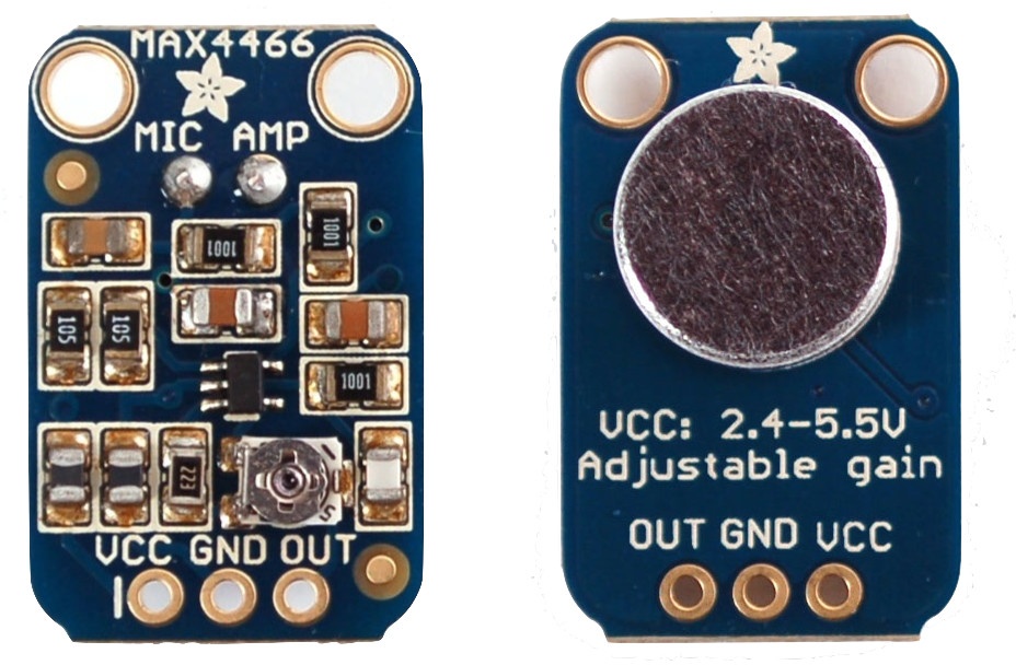
We’re going to use the electret microphone breakout board from Adafruit Industries (see Figure 4-1). The board comes with a capsule microphone and supporting hardware including, an op-amp and a potentiometer to allow you to adjust the gain.
Electret microphones are small, omnidirectional microphones commonly used in cell phones and laptops. They can have an extremely wide frequency response; the one we’re using has a 20Hz to 20kHz frequency response. They are small, very cheap to produce, and quite sensitive. Unfortunately, they also have some drawbacks, including a very uneven frequency response, high noise floor, and high levels of distortion. Despite that, they’re a good choice if fidelity isn’t an overriding issue for your application.
Since the electret microphone only produces a few milli-volts peak-to-peak, it needs to be coupled with an op-amp before it can be used. The Adafruit breakout board uses a Maxim MAX4466 for this purpose.
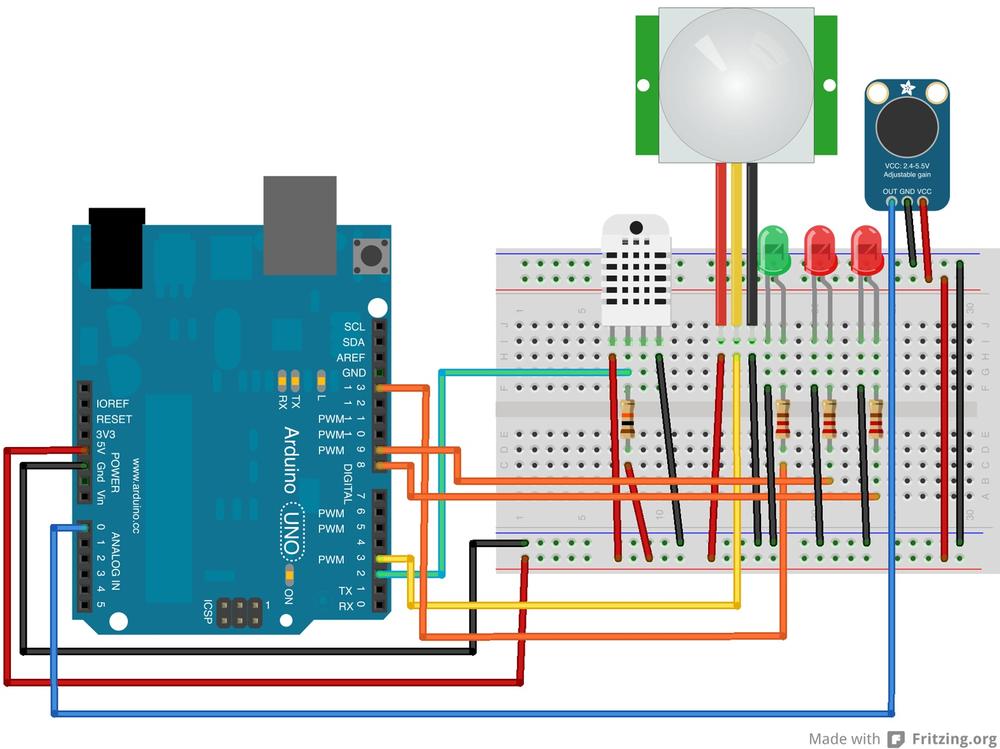
Starting where we left off at the end of the last chapter, let’s go ahead and add the microphone to our current setup (see Figure 4-2).
Looking at the silkscreen on the Adafruit board, you’ll see that there are three connectors (see Figure 4-2 again). Looking at the front, the output (signal) is on the left, labeled OUT; the middle connector is the ground, labeled GND; and the power is on the right, labeled VCC. You’ll also see from the silkscreen that we can drive the board with anything from 2.4V up to 5.5V. That’s good, as our Arduino microcontroller board runs at 5V. We can plug the microphone board directly into the Arduino.
Connect a jumper wire from the +ve (+5V) rail to the VCC connector of the breakout board, and another from the −ve (GND) rail to the GND connector. Finally, connect another jumper wire from the OUT connector on the microphone breakout board to the A0 pin on the Arduino.
Note
The A0 pin on the Arduino is on the lefthand side of the board when you’re looking at it with the USB and power jacks facing away from you. While you can use this pin as a normal digital input/output pin, this is a special pin that can also be used for analog input.
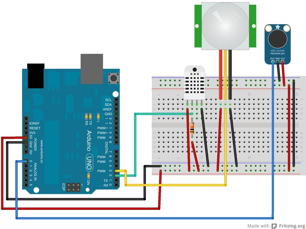
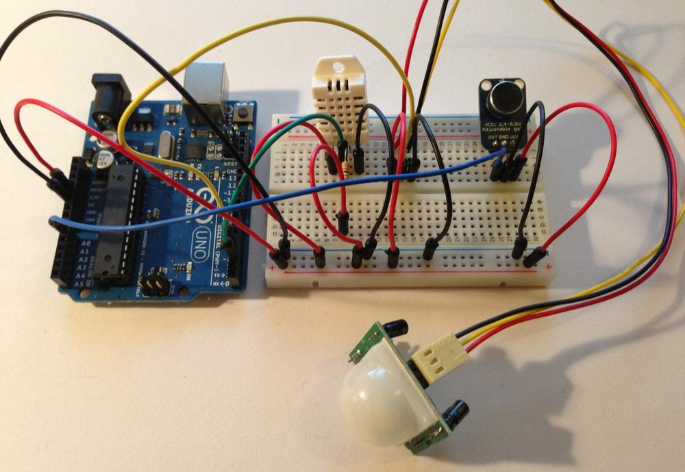
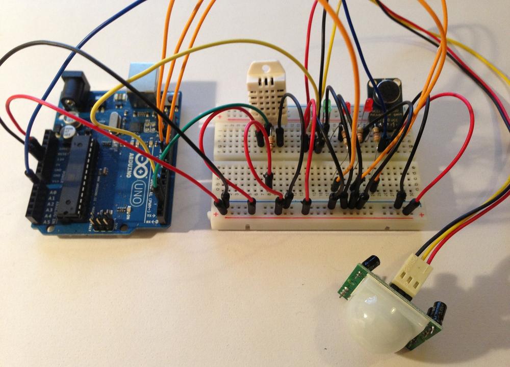
You may notice in Figure 4-3 that we’ve actually wired the breadboard slightly differently from the wiring diagram in Figure 4-2. This is because our microphone breakout board came with three header pins, and instead of connecting the wires to the microphone board, we soldered the headers to it and then plugged that into the breadboard. This really simplified things.
Note
See Chapter 5 for more information about how to solder if you haven’t done any soldering before. If you don’t want to solder the header pins to the microphone board quite yet, you can probably get away with threading some jumper wires through the holes and firmly wrapping them around the board. You’ll need to make sure that they make a good connection to the pad, and that they don’t touch and short each other out.
If you’ve followed the instructions, you should have something that looks a lot like Figure 4-3.
Calibrating sound level readings so that you get a value measured in decibels is actually a really hard to do accurately, so we’re not even going to try here. In any case, we’re really only interested in knowing how the noise level around the sensor platform changes over time, rather than the absolute value of the sound pressure on the microphone.
We can determine this far more easily than measuring an absolute (calibrated) value by keeping a running average of the sound pressure on the microphone and reporting how the current reading has changed with respect to our running average.
Go ahead and make the changes highlighted in bold below to our code:
#include <DHT.h> #define DHTTYPE DHT22 #define SILENT_VALUE 380 // starting neutral mic value (self-correcting)int dhtPin = 2; DHT dht(dhtPin, DHTTYPE); int pirPin = 3; int pirState = LOW; // we start, assuming no motion detected int pirVal = 0; int motionState = 0; int micPin = 0; int micVal = 0; void setup() {
pinMode(dhtPin, INPUT); // declare DHT sensor pin as input pinMode(pirPin, INPUT); // declare PIR sensor pin as input Serial.begin(9600); // open the serial connection to your PC dht.begin(); } void loop() { float h = dht.readHumidity(); float t = dht.readTemperature(); if (isnan(t) || isnan(h)) { Serial.println("Error: Failed to read from DHT"); } else { Serial.print( "T = " ), Serial.print( t ); Serial.print( "C, H = " ); Serial.print( h ); Serial.println( "%" ); } pirVal = digitalRead(pirPin); // read input value if(pirVal == HIGH){ // check if the input is HIGH if(pirState == LOW){ // we have just turned on motionState = 1; Serial.println( "Motion started" ); // We only want to print on the output change, not state pirState = HIGH; } }else{ if(pirState == HIGH){ // we have just turned of motionState = −1; Serial.println( "Motion ended" ); // We only want to print on the output change, not state pirState = LOW; } } micVal = getSound(); Serial.print( "MIC = " ); Serial.println( micVal ); motionState = 0; // reset motion state delay(2000); } int getSound() { static int average = SILENT_VALUE;
static int avgEnvelope = 0;
int avgSmoothing = 10;
int envSmoothing = 2; int numSamples = 1000; int envelope = 0;
for ( int i = 0; i< numSamples; i++ ) { int sound = analogRead(micPin);
int sampleEnvelope = abs(sound - average); envelope = (sampleEnvelope+envelope)/2; avgEnvelope = (envSmoothing * avgEnvelope + sampleEnvelope) / (envSmoothing + 1); average = (avgSmoothing * average + sound) / (avgSmoothing + 1); } return envelope; }
-
The
analogRead()command converts the input voltage range, 0 to 5 volts, to a digital value between 0 and 1023. Here we’re setting the “silent” value to be 380, or around 1.85V. This “background noise” level will self correct over time.-
Since the microphone is producing an analog signal, we don’t have to initialize the A0 pin for either input or output. This isn’t necessary when we’re using the pin in analog mode, because in this mode they can be only be used for input. Without additional hardware, the Arduino cannot produce an analog signal, although it can fake it using Pulse Width Modulation (PWM) on some pins. These pins are marked with a
~symbol on the silkscreen.-
The running average is where the current neutral position for the microphone is stored.
-
The average envelope level is the running average for the sound pressure level.
-
Larger values of
aveSmoothinggive more smoothing for the average, while larger values forenvSmoothinggive more smoothing for the envelope.-
The envelope is the mean sound taken over many samples.
-
Instead of
digitalRead( )we instead useanalogRead( )to get the state of the A0 pin to which our microphone connected. As mentioned above, this will return a digital value between 0 and 1023 representative of the analog voltage level present on the pin.
Once you’ve entered the code, plug your Arduino into your computer, then go ahead and compile and upload the sketch to your board.
Note
See the sections Connecting to the Board and Uploading the Sketch in Chapter 1 if you’re having trouble uploading the sketch to your Arduino board.
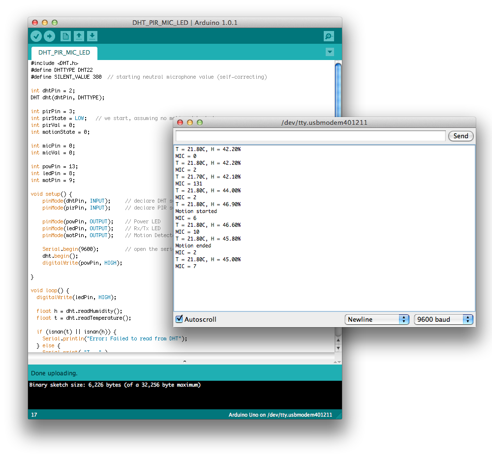
When you see the “Done uploading.” message in the status bar, click on the Serial Console button in the development environment to open the serial console.
Opening the Serial Console will reset the Arduino, at which point you should see something a lot like Figure 4-4. Every couple of seconds, a new reading of the temperature, humidity, and (sound) envelope values will be printed to the console. As before, interspaced with these will be the notifications from the PIR sensor of the beginning and end of any movement.
Note
Remember that the envelope value being reported is not a measurement of the absolute volume of the noise (sound pressure) on the microphone, but instead is a measurement of the change in this noise.
While we have haven’t made use of them much so far, as our Arduino boards have been connected directly to our laptop and we’ve been able to use the serial connection to see what’s going on, LEDs are used almost ubiquitously as a debugging tool when building hardware. Later in the book (see Chapter 7), we’re going to unhook our Arduino from our laptop and put it on the network, and we won’t be able to see the serial output from the board directly any more. So now is a good time to add some LEDs to our project to help us with debugging later on.
We’re going to use three LEDs (see Figure 4-5): one to show that our
board has booted and is turned on, another to show us that it’s running
our loop( ) correctly, and a final one
to show us if there has been any movement detected by the PIR
sensor.
Note
I’m going to use a green LED for power, and two red LEDs for the loop and motion indicator lights. You don’t have to do that; any LED will do.
Insert three LEDs into your breadboard as shown in Figure 4-5, and use a jumper wire to connect the GND pin of each of the LEDs to the −ve (GND) rail of the breadboard.
Warning
Remember that LEDs are directional components and must not be inserted backwards. Look carefully at the two legs of the LED; one should be shorter than the other. The shorter leg corresponds to the ground, while the longer leg is the positive.
Then, in a similar manner to the way we wired the pull-up resistor we used for the DHT-22 sensor, connect a 220Ω resistor to the positive pin of each of the three LEDs, bridging the gap between the two sides of the breadboard. Then use a jumper wire to connect the three LEDs to PINs 13, 9, and 8 on the Arduino board, respectively going left-to-right (see Figure 4-5 again if needed).
Note
A resistor is needed inline between the LED and the Arduino to limit the current flowing across the resistor; if you drive an LED with too high a current, you will destroy it. If you think back to Chapter 1, you’ll remember that we plugged an LED directly into PIN 13 of the Arduino board. While it’s generally okay to do that, it’s not good practice, and you should avoid it now that you know better.
If you’ve followed the instructions and the wired the breadboard as laid out in Figure 4-5, you should have something that looks a lot like Figure 4-6.
Now we’re changed the hardware, it’s time to modify our software.
The changes to our Arduino sketch are pretty self-explanatory.
We’ll set up the three LED pins as OUTPUT in the setup() function and then toggle them
HIGH and LOW depending on what we want to
indicate.
Make the following changes shown in bold to your code:
#include <DHT.h>
#define DHTTYPE DHT22
#define SILENT_VALUE 380  // starting neutral microphone value (self-correcting)

int dhtPin = 2;
DHT dht(dhtPin, DHTTYPE);

int pirPin = 3;
int pirState = LOW;   // we start, assuming no motion detected
int pirVal = 0;
int motionState = 0;

int micPin = 0;
int micVal = 0;

int powPin = 13;
int ledPin = 8;
int motPin = 9;

void setup() {
    pinMode(dhtPin, INPUT);     // declare DHT sensor pin as input
    pinMode(pirPin, INPUT);     // declare PIR sensor pin as input

    pinMode(powPin, OUTPUT);    // Power LED
    pinMode(ledPin, OUTPUT);    // Rx/Tx LED
    pinMode(motPin, OUTPUT);    // Motion Detected LED

    Serial.begin(9600);         // open the serial connection to your PC
    dht.begin();
    digitalWrite(powPin, HIGH);

}

void loop() {
  digitalWrite(ledPin, HIGH);

  float h = dht.readHumidity();
  float t = dht.readTemperature();

  if (isnan(t) || isnan(h)) {
    Serial.println("Error: Failed to read from DHT");
  } else {
    Serial.print( "T = " ),
    Serial.print( t );
    Serial.print( "C, H = " );
    Serial.print( h );
    Serial.println( "%" );
  }

  pirVal = digitalRead(pirPin);  // read input value
  if(pirVal == HIGH){            // check if the input is HIGH
    if(pirState == LOW){
      // we have just turned on
      motionState = 1;
      digitalWrite(motPin, HIGH);  // turn LED ON
      Serial.println( "Motion started" );


      // We only want to print on the output change, not state
      pirState = HIGH;
    }
  }else{
    if(pirState == HIGH){
      // we have just turned off
      motionState = −1;
      digitalWrite(motPin, LOW);  // turn LED OFF
      Serial.println( "Motion ended" );

      // We only want to print on the output change, not state
      pirState = LOW;
    }
  }

  micVal = getSound();
  Serial.print( "MIC = " );
  Serial.println( micVal );

  motionState = 0; // reset motion state
  digitalWrite(ledPin, LOW);
  delay(2000);

}

int getSound() {
  static int average = SILENT_VALUE;
  static int avgEnvelope = 0;
  int avgSmoothing = 10;
  int envSmoothing = 2;
  int numSamples=1000;
  int envelope=0;
  for (int i=0; i<numSamples; i++) {
    int sound=analogRead(micPin);
    int sampleEnvelope = abs(sound - average);
    envelope = (sampleEnvelope+envelope)/2;
    avgEnvelope = (envSmoothing * avgEnvelope + sampleEnvelope) /
                  (envSmoothing + 1);
    average = (avgSmoothing * average + sound) / (avgSmoothing + 1);
  }
  return envelope;
}
Once you’ve entered the code, plug your Arduino into your computer, then go ahead and compile and upload the sketch to your board.
Note
See the sections Connecting to the Board and Uploading the Sketch in Chapter 1 if you’re having trouble uploading the sketch to your Arduino board.
When you see the “Done uploading.” message in the status bar, click on the Serial Console button in the development environment to open the serial console.
If you open up the serial console in the Arduino development environment, everything should pretty much be exactly the same as before. However, this time there should be some blinking lights to accompany your data (see Figure 4-7).
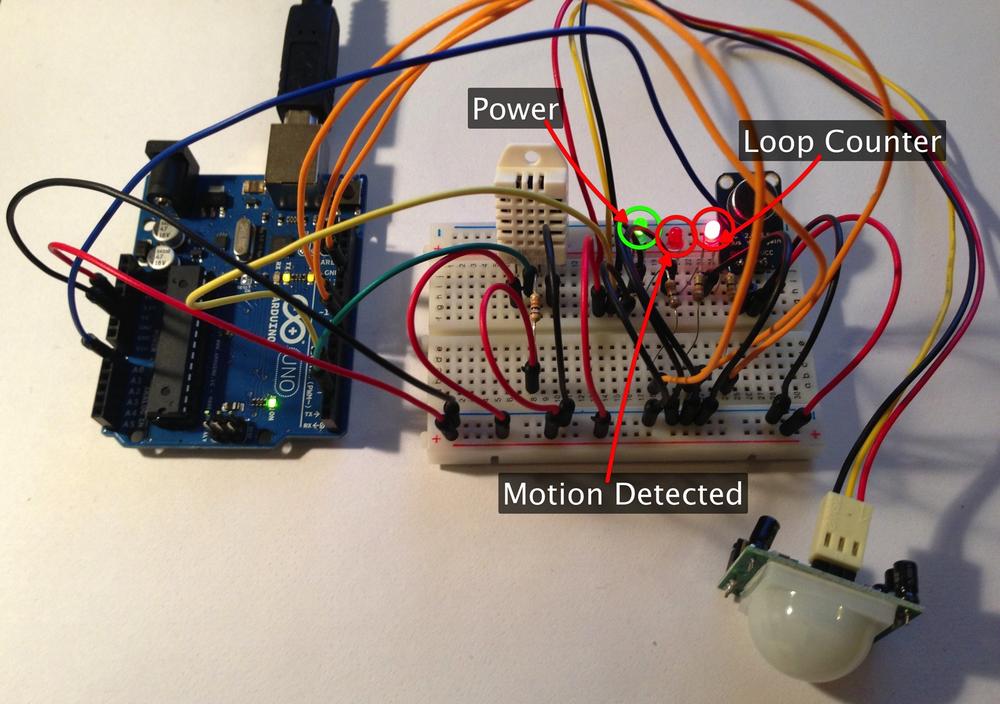
Figure 4-7. The LEDs show the current state of the sketch, and are helpful for monitoring our board when we unplug it from our laptop
The leftmost LED should turn on at the end of the setup() function and stay on: this is the LED
we’re using to indicate that the power to the board is on and our sketch
has started. The rightmost LED should be pulled high (and thus turn on)
at the start of the loop() function,
and then be pulled low (and thus turn off) after the loop completes.
This means that the LED will slowly blink on and off, showing us that
data is being taken. Finally, the middle LED should be pulled high (and
turn on) when the PIR sensor detects the start of motion, and then low
again (and turn off) at the end of motion.
Right now the output of our sketch to the serial port was designed to be read by a human. However, in the next chapter we’re going use some Python code to collect our data and save it to a CSV file on disk so we can examine it afterwards, and do some visualization. For that, we’re going to have to make some changes to the output of our sketch.
We only really need to modify serial output in the loop( )—the rest of our code can stay the
same:
void loop() {
  digitalWrite(ledPin, HIGH);

  float h = dht.readHumidity();
  float t = dht.readTemperature();

  if (isnan(t) || isnan(h)) {
    // Don't output temperature and humidity readings
  } else {
    Serial.print( t );
    Serial.print( ", " );
    Serial.print( h );
    Serial.print( ", " );
  }

  pirVal = digitalRead(pirPin);  // read input value
  if(pirVal == HIGH){            // check if the input is HIGH
    if(pirState == LOW){
      // we have just turned on
      motionState = 1;
      digitalWrite(motPin, HIGH);  // turn LED ON

      // We only want to print on the output change, not state
      pirState = HIGH;
    }
  }else{
    if(pirState == HIGH){
      // we have just turned off
      motionState = −1;
      digitalWrite(motPin, LOW);  // turn LED OFF

      // We only want to print on the output change, not state
      pirState = LOW;
    }
  }

  micVal = getSound();
  Serial.print( micVal );
  Serial.print( ", " );

  Serial.print( pirVal );
  Serial.print( ", " );
  Serial.println( motionState );

  motionState = 0; // reset motion state
  digitalWrite(ledPin, LOW);
  delay(2000);

}
After making these changes, re-upload the sketch to your hardware. If you reopen the serial console, the output from the sketch should be changed from this:
T = 22.60C, H = 42.50%
MIC = 14
T = 22.50C, H = 42.60%
MIC = 25
Motion Started
T = 22.50C, H = 42.60%
MIC = 25
T = 22.60C, H = 42.60%
MIC = 30
T = 22.70C, H = 42.70%
MIC = 114
Motion Ended
T = 22.60C, H = 42.70%
MIC = 20
to something more like this:
22.60, 42.50, 14, 0, 0
22.50, 42.60, 25, 1, 1
22.60, 42.60, 30, 1, 0
22.70, 42.70, 114, 1, −1
22.60, 42.70, 20, 0, 0…as we can see in Figure 4-8.
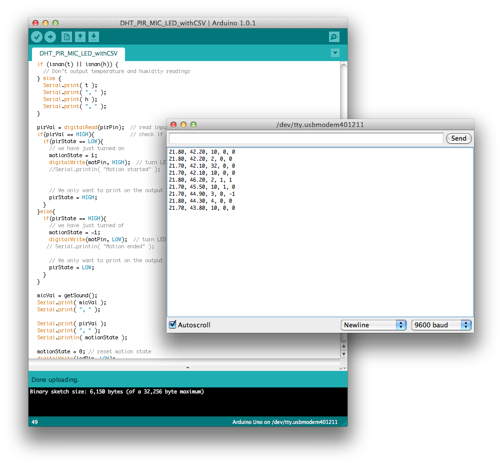
This will be a lot easier to read into Python—or any other sort of code—than the more human-friendly but hard-to-parse output we had before.
We will use Python as a quick tool to talk to our Arduino. If you haven’t used Python before, there are many tutorials and books that will help get you started. Our intention here is to give you the code required to connect to the Arduino and start receiving data.
First, make sure you have the pySerial module installed on your computer. Although the Arduino is connected via a USB port, it uses the computer’s serial interface protocols for communication.
To talk to the Arduino, we need to find the port that the Arduino is connected to. On a typical Macintosh, the Arduino will show up as a USB modem device:
%python -m serial.tools.list_ports
/dev/tty.Bluetooth-Modem
/dev/tty.Bluetooth-PDA-Sync
/dev/tty.usbmodem621
3 ports found
%
Your ports may not look exactly like this, but should be similar.
Once you have found a USB modem device that looks promising, use the
ser command to open the serial port
in order to talk to the Arduino. Make sure you have first imported the
serial library into Python.
>>> import serial
>>> ser = serial.Serial('/dev/tty.usbmodem621')
If you get any errors, try another one of the serial ports. If that doesn’t work, make sure no other devices are currently using the serial port in question. Unplug and then reconnect your Arduino to make sure the port is not in use. Once you have successfully opened the serial port, the following quick test will confirm a working connection:
>>> x = ser.read(30)
>>> print x
If you are running the demo code from the sensor mote project, you should see a printout that looks like this:
22.60, 42.50, 14, 0, 0
After you have tested your connection using the Python command line, feel free to close the serial port:
>>> ser.close()
We can take our Python code a step further. The following Python script will collect time-stamped data from your sensor mote and save it to a .csv file:
import serial
import time

ser = serial.Serial('/dev/tty.usbmodem621', 9600, timeout=1)
time.sleep(1)

logfile = open('test.csv', 'a')

count = 0
while (count < 5):
    count = count + 1
    line = ser.readline()
    now = time.strftime("%d/%m/%Y %H:%M:%S", time.localtime())
    a =  "%s, %s, %s" % (now, line, "\n")
    print a
    logfile.write(a)
    logfile.flush()
logfile.close()
ser.close()
Once you have confirmed that you can collect data and send it to a log file, you have completed the steps required to build a sensor mote by hand and connect it to your computer.
Note
If you are interested in being able to move your data from the Arduino to a TCP connection, this can be done simply by downloading and implementing a Python TCP to Serial bridge example.
Get Distributed Network Data now with the O’Reilly learning platform.
O’Reilly members experience books, live events, courses curated by job role, and more from O’Reilly and nearly 200 top publishers.

