Figure 4-1 shows the major components of the SOHO server. The Intel Server Chassis SC5250-E is flanked on the left by the Plextor PX-708A DVD writer and a Seagate External Hard Drive, and on the right by the Intel S875WP1-E server motherboard. In front of them, left to right, are four Seagate Barracuda 7200.7 SATA hard drives and the retail-boxed Pentium 4 CPU. Two 256 MB sticks of Crucial memory are located front and center.

Make sure you have everything you need before you start building the system. Open each box and verify the contents against the packing list. Once again, we failed to follow that advice, and once again we got bit. This time, it was because we made what seemed at the time to be a reasonable assumption. The Intel SC5250-E specifications list support for four Serial ATA hard drives. We foolishly assumed that meant the power supply provided power connectors for at least four S-ATA drives. Wrong.
The Intel power supply provides zero S-ATA power connectors. For some S-ATA drives, that wouldn’t matter, because they have both S-ATA power connectors and standard (Molex) power connectors. Alas, the Seagate S-ATA drives have only S-ATA power connectors. We were stuck until we could come up with adapter cables to connect the Seagate S-ATA drives to the standard connectors on the Intel power supply.
Note
As it turns out, we can’t blame Intel for not including S-ATA power connectors. The SC5250-E case has many options, one of which is an S-ATA backplane that supports hot-swapping S-ATA hard drives. We didn’t order that option because it cost more than $100 and we had no real need for hot-swap support. If we had ordered that option, we would have had no problem powering our S-ATA drives.
You might think that S-ATA power adapter cables would be easy to come by. You’d be wrong. We called the local computer stores, Best Buy, Office Depot, and every other place we could think of that might stock such adapter cables. No luck. Most of them didn’t even know what we were talking about. Those that did had none in stock and no idea where to get them. We then searched several of our usual online vendors and found that they didn’t have what we needed either. We couldn’t even find any on the Belkin and Cables-to-Go web sites.
We were surprised, to say the least. This isn’t rocket surgery. S-ATA hard drives are becoming common, and only the newest power supplies provide S-ATA power connectors. One would think these adapter cables would be available everywhere. Nope. We wasted hours trying to find four lousy $3 cables.
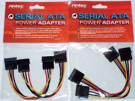
Antec to the rescue! We finally thought to check the Antec web site, where we found the Antec Serial ATA power adapter cables shown in Figure 4-2. We needed four adapters. They come two to a package, so we ordered five packages. We’re not going to go through this again. We’ll scatter Serial ATA power adapter cables throughout our tool kits, on our workbench, and with our spare S-ATA drives in the inventory room. Never again.
Note
As always, you needn’t follow the exact sequence of steps we describe when you build your own SOHO server. Always install the processor before you install the motherboard in the case, because doing otherwise risks damaging the processor, but the exact sequence doesn’t matter for most other steps. Some steps must be taken in the order we describe because completing one step is required for completing the next, but as you build your system it will be obvious when sequence matters.
The first step in building any system is always to make sure that the power supply is set to the correct input voltage. Some power supplies—including the Intel 450W unit supplied with the SC5250-E case—set themselves automatically. Others must be set manually using a slide switch to select the proper input voltage.
Warning
If your power supply must be set manually for input voltage, make absolutely certain you’ve set the proper voltage before you connect anything to the power supply. If your power receptacle provides 115V and the power supply is set to 230V, the system won’t boot, but nothing will be damaged. But if you connect a power supply set for 115V to a 230V receptacle, turning on the system will destroy all components instantly.
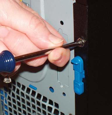
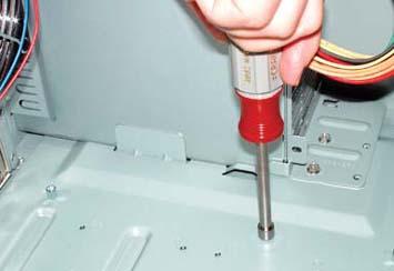
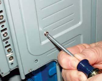
To begin preparing the SC5250-E case, remove the two screws that secure the side panel, as shown in Figure 4-3. We call them “shipping screws” because they’re there primarily to keep the side panel securely in place during shipping. Although you can insert these screws again after you finish building the system, it really isn’t necessary. The side-panel latch by itself is sufficient to secure the side panel during routine use.
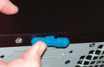
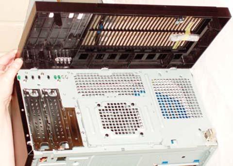
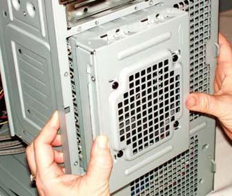
After you remove the screws that secure the side panel, slide the two blue plastic locking tabs to the unlocked position, as shown in Figure 4-4, and lift the side panel off.
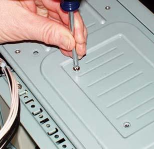
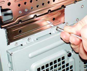
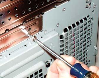
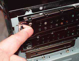
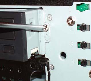
With the side panel removed, remove the two screws that secure the hard drive bay to the side of the case, as shown in Figure 4-5.
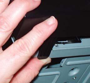
The next step is to remove the front bezel. To do so, place the case in a vertical position and press the two plastic locking tabs on the left side of the bezel, as shown in Figure 4-6. Then swing the bezel to the right and lift it off, as shown in Figure 4-7.
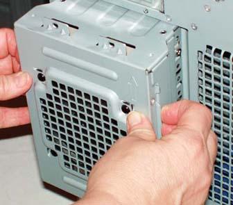
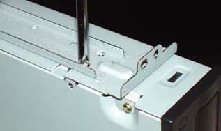
With the bezel removed, remove the two screws that secure the hard drive bay to the front of the case, as shown in Figure 4-8. Grasp the hard drive bay firmly and slide it out of the chassis, as shown in Figure 4-9.
The Intel SC5250-E chassis is one of very few cases that come without a standard I/O template. That saves us the usual step of removing the standard template, which almost never matches the back-panel I/O ports of whatever motherboard we happen to be installing, and replacing it with the template supplied with the motherboard.
Locate the I/O template in the S875WP1 motherboard box, and compare it to the back-panel I/O ports on the motherboard to verify that it’s the correct template. Align the template with the I/O template cutout in the case, as shown in Figure 4-10.

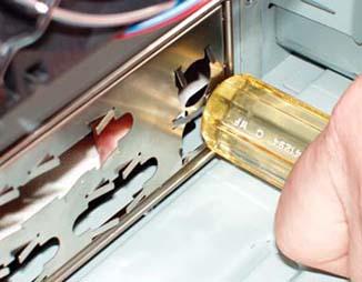
With the template aligned, press gently along the edges until it snaps into place. If you have trouble getting the template to seat, you’re not alone. Some easily snap right into place, but others simply refuse to seat without extraordinary effort. Just as you get one side popped into place, another pops free. Or you get three of them aligned, and the fourth just refuses to seat. The best way we’ve found to seat recalcitrant templates is to work our way toward one corner, getting everything aligned as we go. Once everything but that one corner is in place, we press gently with a tool handle, as shown in Figure 4-11, until the final corner seats.
Warning
Be careful not to bend the I/O template while seating it. The template holes need to line up with the external port connectors on the motherboard I/O panel. If the template is even slightly bent it may be difficult to seat the motherboard properly.
After you install the I/O template, carefully slide the motherboard into place, making sure that the back-panel connectors on the motherboard are firmly in contact with the corresponding holes on the I/O template. Compare the positions of the motherboard mounting holes with the stand-off mounting positions in the case. If you simply look at the motherboard, it’s easy to miss one of the mounting holes in all the clutter. We generally hold the motherboard up to a light, which makes the mounting holes stand out distinctly.
The Intel S875WP1 motherboard has nine mounting holes. The Intel SC5250-E, like many cases, is shipped with several standoffs preinstalled; unlike some cases, it labels all standoff mounting hole positions. The S875WP1 motherboard requires standoffs at positions A, E, and K, which have standoffs preinstalled, and at positions 1, 3, L, C, H, and M, which do not.
Note
There is also a standoff preinstalled at position D. Ordinarily, it’s necessary to remove superfluous standoffs to avoid shorting out the motherboard. However, the SC5250-E case is designed to accept oversized motherboards, which are the only ones that contact position D. In this case, the extra standoff does not interfere and can be removed or left in place at your option.
It is immediately apparent even to the casual eye that the mounting hardware supplied with the Intel case is a cut above the mounting hardware supplied with even top-notch cases like those from Antec and PC Power & Cooling. Rather than the typical 5mm brass standoffs, Intel supplies 6mm plated standoffs. All parts are separated by type in individual plastic baggies.
The standoffs are in Bag E. Remove six of them from the bag, and use a 6mm nut driver to install them at positions 1, 3, L, C, H, and M, as shown in Figure 4-12. Tighten the standoffs finger-tight, but no more.
After you install all the standoffs, verify that each motherboard mounting hole has a standoff, and that no standoffs are installed that don’t correspond to a motherboard mounting hole. Then slide the motherboard into position, as shown in Figure 4-13, to verify that everything aligns properly.
The steps detailed in the following sections prepare the motherboard by installing the processor, heatsink/fan unit, and memory.
Warning
Before you handle the processor, memory, or other static-sensitive components, touch the power supply to ground yourself.
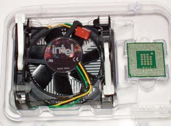
For this system we used a retail-boxed Pentium 4 processor, which includes the processor itself and an Intel-branded heatsink/fan unit, as shown in Figure 4-14. The plastic bubble-wrap packaging Intel uses is truly obnoxious. We did eventually get the package open using scissors, but for a time we thought we’d have to resort to a chainsaw.
Warning
Don’t make the mistake of trying to pry the package open using just your fingers. Robert did that once with an Intel retail-boxed processor. When the package finally popped, the heatsink/fan unit went sailing across the room and the processor landed in his lap. (Thank goodness it wasn’t the other way around.)
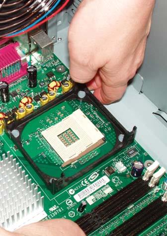
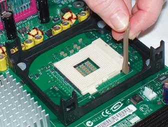
To install the Pentium 4 processor, lift the arm of the ZIF (zero insertion force) socket until it reaches vertical, as shown in Figure 4-15. With the arm vertical, there is no clamping force on the socket holes, which allows the processor to drop into place without requiring any pressure.
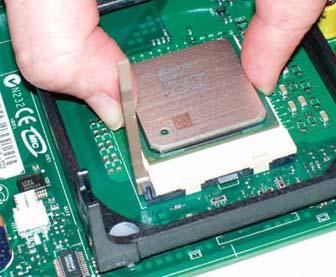
Correct orientation is indicated on the processor by a trimmed corner and on the socket by a small triangle, both visible in Figure 4-16 near the ZIF socket lever. With the socket lever vertical, align the processor with the socket and drop the processor into place, as shown in Figure 4-16. The processor should seat flush with the socket just from the force of gravity, or with at most a tiny push. If the processor doesn’t simply drop into place, something is misaligned. Remove the processor and verify that it is aligned properly and that the pattern of pins on the processor corresponds to the pattern of holes on the socket.
Warning
Never apply pressure to seat the processor—you’ll bend the pins and destroy the processor. Note that closing the ZIF level may cause the processor to rise up slightly from the socket. After the processor is fully seated, it’s safe to apply gentle pressure with your finger to keep it in place as you close the ZIF lever.
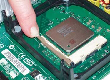
With the processor in place and seated flush with the socket, press the lever arm down and snap it into place, as shown in Figure 4-17. You may have to press the lever arm slightly away from the socket to allow it to snap into a locked position.
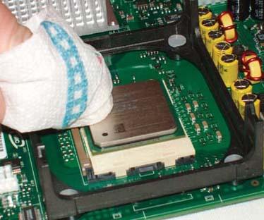
To install the HSF unit, begin by polishing the heat spreader surface on top of the processor with a paper towel or soft cloth, as shown in Figure 4-18. Make sure to remove any grease, grit, or other material that might prevent the heatsink from making intimate contact with the processor surface.
Note
If the processor has previously been used, clean off any remaining thermal compound or thermal-pad remnants before you install the heatsink/fan unit. You can remove old thermal compound using Goof-Off or isopropyl alcohol on a cloth, or by polishing the processor gently with 0000 steel wool. Steel wool is conductive, so make absolutely sure no stray bits of it remain after you finish polishing the processor. Even a tiny piece of steel wool can short out the processor or another motherboard component, with disastrous results.
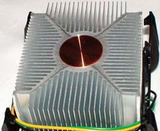
Next, check the contact surface of the heatsink, shown in Figure 4-19. If the heatsink base is bare, that means it’s intended to be used with thermal compound, usually called “thermal goop.” In that case, polish the heatsink base as well.
Note
The heatsink shown in Figure 4-19 is a so-called “AlCu” hybrid unit, for the chemical symbols for aluminum and copper. The body of the heatsink is made from aluminum, and the contact surface for the processor from copper. Copper has better thermal properties, but is much more costly than aluminum.
Inexpensive heatsinks and those designed for slower, cooler-running processors use aluminum exclusively. Heatsinks designed for fast, hot-running processors (and for overclockers) use copper exclusively. Hybrid heatsinks balance cost and performance by using copper only where heat transfer properties are critical.
Alternately, some heatsinks have a square or rectangular pad made of a phase-change medium, which is a fancy term for a material that melts as the CPU heats and resolidifies as the CPU cools. This liquid/solid cycle ensures that the processor die maintains good thermal contact with the heatsink. If your heatsink includes such a pad, you needn’t polish the base of the heatsink. (Heatsinks use either a thermal pad or thermal goop, not both.)
Note
Don’t worry if your heatsink or thermal compound doesn’t exactly match those we illustrate in this chapter. The type of heatsink and thermal compound supplied with Intel retail-boxed processors varies from model to model, and may also vary within a model line.
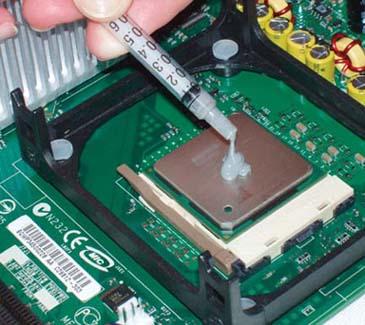
Intel never uses a cheap method when a better solution is available, and the packaging for their thermal compound is no exception. Rather than the usual single-serving plastic packet of thermal goop, Intel provides thermal goop in a syringe with a pre-measured dose. To apply the thermal goop, put the syringe tip near the center of the processor and squeeze the entire contents of the syringe onto the processor surface, as shown in Figure 4-20.
Note
Incidentally, the pre-measured thermal goop syringe shown here illustrates the proper amount of goop for a Pentium 4 processor. If you’re applying goop from a bulk syringe, squeeze out only the amount shown here, about 0.1 milliliter (mL), which may also be referred to as 0.1 cubic centimeter (CC). Most people tend to use too much.
If you apply too much thermal goop, the excess squooshes out from between the HSF base and the processor surface when you put the heatsink in place. Good practice suggests removing excess goop from around the socket, but that may be impossible with a large heatsink because the heatsink blocks access to the socket area. Standard silicone thermal goop does not conduct electricity, so there is no danger of excess goop shorting anything out.
If you’re a neatnik, use your finger (covered with a latex glove or plastic bag) to spread thin layers of goop on the processor surface and heatsink base before you install the HSF. We do that with silver-based thermal compounds, which we don’t trust to be electrically non-conductive, despite manufacturers’ claims to the contrary.
Warning
If you remove the heatsink, you must replace the thermal compound or pad when you reinstall it. Before you reinstall, remove all remnants of the old thermal pad or compound. This can be difficult, particularly for a thermal pad, which can be very tenacious. We use an ordinary hair dryer to warm the thermal material enough to make it easy to remove. Sometimes the best way is to warm up the compound and rub it off with your thumb.
When we replace a heatsink, we use Antec Silver Thermal Compound, which works well and is widely available and inexpensive. Don’t pay extra for “premium” brand names like Arctic Silver. They cost more than the Antec product, and our testing shows little or no difference in cooling efficiency.
The next step is to orient the HSF above the processor, as shown in Figure 4-21, keeping it as close to horizontal as possible. Slide the HSF unit down into the retaining bracket, making sure that the lock tabs on each of the four corners of the HSF assembly are aligned with the matching slots in the HSF retaining bracket on the motherboard. Press down gently and use a small circular motion to spread the thermal goop evenly over the surface of the processor.
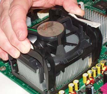
Figure 4-21. Align the HSF unit over the processor, making sure the locking tabs on the HSF align with the corresponding slots on the HSF retaining bracket
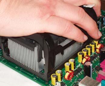
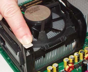
Make sure that both of the white plastic cam levers (one is visible near Barbara’s thumb in Figure 4-21) are in the open position, not applying any pressure to the HSF mechanism. With the HSF aligned properly, press down firmly, as shown in Figure 4-22, until all four HSF locking tabs snap into place in the corresponding slots on the HSF retaining bracket. This step requires applying significant pressure evenly to the top of the HSF mechanism, so it’s generally easier to use your whole hand rather than just your fingers or thumb.
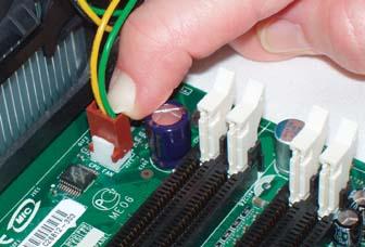
With the HSF snapped into the HSF retaining bracket, the next step is to clamp the HSF tightly against the processor to ensure good thermal transfer between the CPU and heatsink. To do this, pivot the white plastic cam levers from their unlocked position to the locked position, as shown in Figure 4-23.
Warning
The first lever is easy to lock into position because there is not yet any pressure on the mechanism. With the first lever cammed into its locked position, though, locking the second lever requires significant pressure. So significant, in fact, that the first time we tried to lock the second lever, we actually popped it out of the bracket. If that happens to you, unlock the first cam lever and snap the second one back into position. You may need to squeeze the pivot point with one hand to keep that lever from popping out of place again while you lock the first lever with the other hand.
The thermal mass of the heatsink draws heat away from the CPU, but the heat must be dissipated to prevent the CPU from overheating as the heatsink warms up. To dispose of excess heat as it is transferred to the heatsink, most CPU coolers use a small muffin fan to continuously draw air through the fins of the heatsink.
Some CPU fans attach to a drive power connector, but most (including this Intel unit) attach to a dedicated CPU fan connector on the motherboard. Using a motherboard fan power connector allows the motherboard to control the CPU fan, reducing speed for quieter operation when the processor is running under light load and not generating much heat, and increasing speed when the processor is running under heavy load and generating more heat. The motherboard can also monitor fan speed, which allows it to send an alert to the user if the fan fails or begins running sporadically.
To connect the CPU fan, plug the keyed cable from the CPU fan into the three-pin header connector on the motherboard labeled “CPU Fan,” as shown Figure 4-24.
Before you install memory modules, take a moment to determine the best memory configuration. The Intel S875WP1 motherboard supports dual-channel memory operation that doubles memory throughput relative to single-channel memory operation. Enabling dual-channel memory requires installing memory modules in pairs in specific DIMM slots, one per channel. Installing two DIMMs in one channel and none in the other channel forces single-channel operation.
Examining the S875WP1 motherboard, we see that it has four DIMM slots in two pairs. The slot nearest the processor is Channel A, DIMM 1, followed by Channel A, DIMM 2, Channel B, DIMM 1, and Channel B, DIMM 2. We want to install one memory module in Channel A and the other in Channel B. We could use either slot, but as a matter of good practice we decided to install our DIMMs in the first (DIMM 1) slot of each channel.
Note
The S875WP1 numbers DIMM slots differently from other Intel motherboards—all other Intel motherboards we are familiar with number the first DIMM slot as 0 and the second as 1. The S875WP1 numbers the first DIMM slot as 1 and the second as 2. Best practice is to install DIMMs beginning with the first slot, whether it is numbered 0 or 1.
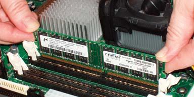
Locate the Channel A DIMM 1 socket and pivot the locking tabs on both sides outward. Align the edges of the first DIMM with the slots in the locking tabs and press firmly with both thumbs to seat the DIMM in the slot, as shown in Figure 4-25. Install the second DIMM in the Channel B DIMM 1 socket in the same manner.
Note
Most DIMM sockets have two parts: a vertical post with an alignment slot, and a pivoting locking tab. Pressing the DIMM down into the alignment slot on the post automatically pivots the locking tab up into the locked position. The S875WP1 DIMM socket hardware is different. The alignment slot is part of the pivoting locking tab, which makes it a bit harder to get the DIMM aligned on both sides. We also found that it was more difficult to seat the DIMM because it was not in full contact with the alignment slot in the early part of its travel. The DIMM tended to wobble as we pressed down, and we were concerned that we might fracture the DIMM by pressing on it while it was unsupported. Be very careful installing DIMMs in this motherboard.
Installing the motherboard is usually the most time-consuming step in building a system because there are so many cables to connect. At times, it has taken us half an hour or more just to get all the cables connected and verified. The Intel S875WP1 reduces the effort needed by combining what would be individual cables on most systems into a monolithic connecting block. Plug in one connector, and you’ve connected all of the front-panel switches and indicators in one swell foop—if, that is, the case provides a matching connector cable. The SC5250-E case does provide that cable, thank goodness.
To begin installing the motherboard, slide it into the case. Carefully align the back-panel I/O connectors with the corresponding holes in the I/O template, and slide the motherboard toward the rear of the case until the motherboard mounting holes line up with the standoffs you installed earlier.
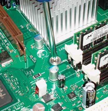
Before you insert any motherboard mounting screws, verify that the back-panel I/O connectors mate properly with the I/O template and that none of the grounding tabs on the I/O template is blocking a port connector. Then insert a screw through one mounting hole into the corresponding standoff, as shown in Figure 4-26. You may need to apply pressure to keep the motherboard positioned properly until you have inserted two or three screws. Use the screws from the bag labeled “A.”
If you have trouble getting all the holes and standoffs aligned, insert two screws but don’t tighten them completely. Use one hand to press the motherboard into alignment, with all holes matching the standoffs. Then insert one or two more screws and tighten them completely. Finish mounting the motherboard by inserting screws into all nine standoffs and tightening them.
Once the motherboard is secured, the next step is to connect the front-panel switch and indicator cable to the motherboard. The S875WP1 uses a 34-pin header to provide connections for all front-panel switches and indicators, including power, reset, and LED indicators. Table 4-4 lists the pinouts for this connector, which is located near the left front edge of the motherboard and is labeled J7J1. (We include these pinouts in case you install this motherboard in a different case.)
Table 4-5. Pinouts for front-panel connector block (J7J1)
|
Pin |
Signal name |
Pin |
Signal name |
|---|---|---|---|
|
1 |
Power LED Anode |
2 |
5Vsb |
|
3 |
Key (no pin) |
4 |
Unused |
|
5 |
GND |
6 |
Unused |
|
7 |
HDD Activity LED Anode |
8 |
Unused |
|
9 |
HDD Activity LED Cathode |
10 |
Unused |
|
11 |
Power Switch |
12 |
NIC#1 Activity LED Anode |
|
13 |
GND (Power Switch) |
14 |
NIC#1 Activity LED Cathode |
|
15 |
FP_RST |
16 |
l1C SDA |
|
17 |
GND (Reset Switch) |
18 |
l2C SDA |
|
19 |
ACPI Sleep Switch |
20 |
Chassis Intrusion |
|
21 |
GND (ACPI Sleep Switch) |
22 |
NIC#2 Activity LED Anode |
|
23 |
Unused |
24 |
NIC#2 Activity LED Cathode |
|
25 |
Key (no pin) |
26 |
Key (no pin) |
|
27 |
Unused |
28 |
Unused |
|
29 |
Unused |
30 |
Unused |
|
31 |
Unused |
32 |
Unused |
|
33 |
Unused |
34 |
Unused |
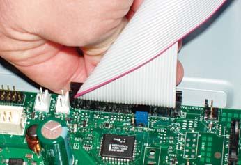
The SC5250-E case has a connecting cable preinstalled on the front-panel side. The loose end of that cable is taped to the case near the left front edge of the motherboard. The cable looks exactly like a floppy drive cable, for which we mistook it when we first noticed it.
Peel the tape off to free the cable, align the cable connector with the motherboard front-panel connector (J7J1), and press the cable connector into place, as shown in Figure 4-27. Note that the cable connector is keyed with blocked holes that correspond to missing pins on the J7J1 connector.
The SC5250-E case includes a preinstalled front-panel USB connecting cable. The motherboard end of that cable is taped to the case near the left edge of the motherboard. The motherboard has a corresponding socket located between the AGP slot and the PCI slot nearest it. The connectors are keyed with a blocked hole and latch. Peel the tape off to free the cable, align the cable plug with the motherboard USB socket, and press the plug into place, as shown in Figure 4-28.
The next step is to install the hard drives, all four of them. We removed the hard drive bay from the SC5250-E case and set it aside earlier. Locate the hard drive bay and the bag of screws labeled “A.” These are the same screws you used to secure the motherboard.
The Intel SC5250-E drive bay has positions for six 3.5” drives. As shipped, the top and bottom positions are blocked by plastic spacers, leaving room for four drives. The plastic spacers channel the airflow from the drive bay fan around the drives to ensure proper cooling.
To mount the hard drives, slide them into the drive bay and secure each one with four screws from the “A” bag, as shown in Figure 4-29.
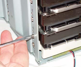
Figure 4-29. Slide the four hard drives into the drive bay and secure each of them with four screws (drive bay fan cable visible at bottom)
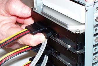
The Intel power supply provides only standard (“Molex”) hard drive power connectors, and the Seagate S-ATA hard drives have only S-ATA power connectors. Therefore, an adapter is needed to power each hard drive. Connect the S-ATA end of an Antec S-ATA power adapter cable to each of the hard drives, as shown in Figure 4-30.
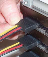
Figure 4-30. If your power supply does not provide S-ATA power connectors, attach an S-ATA power adapter cable to each hard drive
Note
Skip this step if your power supply provides S-ATA power connectors, or if you are using S-ATA hard drives that provide standard Molex power connectors.
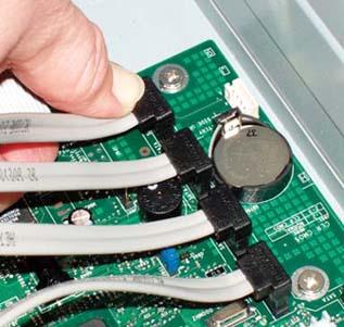
The next step is to connect an S-ATA data cable to each of the hard drives, as shown in Figure 4-31. Orient the cable connector so that its key is aligned with the key on the drive connector and then press the cable connector into place until you feel it seat.
Note
We are configuring our four hard drives as a RAID 0+1 array to protect against data loss if a drive fails. When a drive fails, you need to know which drive to replace. The computer tells you which interface is connected to the problem drive, but you have to use that information to determine which physical drive has failed.
With the rats’ nest of connecting cables inside the server, it can be difficult to determine which drive is connected to which interface, particularly after those cables are tied off and dressed. Accordingly, we always mark both ends of each cable. Use a felt-tip marker to draw a line across the end of each cable—one line on each end for Drive 1, two lines for Drive 2, and so on. (On dark cables, a white-out pen produces more visible markings.)
Warning
Be careful when connecting S-ATA power and data cables. The connectors, while not fragile, are not as robust as old-style parallel ATA power and data connectors. Install the cables by pressing straight in on the connectors, and remove them by pulling straight out. Avoid putting any lateral pressure on the connectors.
With the drives secured in the bay and the S-ATA data cables and power adapters connected, the next step is to reinstall the drive bay in the case. Begin by feeding the cables through from the front of the case. Then position the drive bay as shown in Figure 4-32 and slide it into place, making sure than none of the cables jams.
Press the drive bay to seat it flush with the case, making sure that the screw holes immediately beneath the floppy disk drive bay align with the corresponding holes in the chassis. Locate the two screws you removed when you removed the drive bay and use them to secure the drive bay to the front of the case, as shown in Figure 4-33.
Then, locate the remaining two screws that you removed when you removed the drive bay, and use them to secure the drive bay to the side of the case, as shown in Figure 4-34.
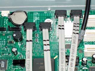
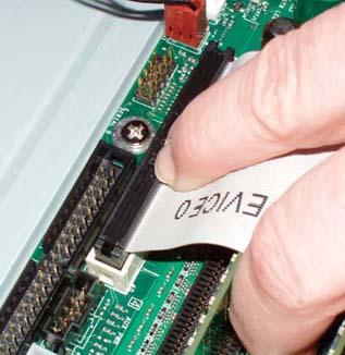
It’s now time to connect the cables. Begin by locating the S-ATA data connectors near the left front corner of the motherboard (this might turn out to be more complicated than you think, so be sure to read the upcoming warning). Route the cables carefully to avoid tangling them with other cables. The goal is to have all four cables together so that you can later tie them off and dress them as a separate bundle. Place each S-ATA data cable connector on a motherboard connector, making sure the keying slots on the cable and motherboard port are aligned. Press the cable connector firmly until you feel it seat. Don’t forget to use a felt-tip pen to label each cable.
Note
Oops. Silly us. The S875WP1 motherboard is available in two versions, one with two Intel S-ATA connectors, and the second with two Intel S-ATA connectors and four additional S-ATA connectors driven by a Promise S-ATA RAID chip. Seeing four connectors in a row and two more off to the side, we assumed (doing that gets us every time) that the four together were the Promise RAID connectors and the two off by themselves were the standard Intel S-ATA connectors. Wrong. Figure 4-35 shows how we first connected the S-ATA cables. The two S-ATA connectors nearest the front of the motherboard (Barbara is pressing a cable onto one) are the “standard” S-ATA connectors, which are labeled “B.” The Promise-based S-ATA RAID connectors are the four nearest the rear of the case, all labeled “A.” Fortunately, we noticed and corrected our error before we reassembled the system. The correct connections are shown in Figure 4-36 (and yes, the connectors are in the order 1-3-2-4).
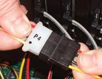
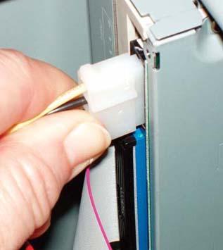
The next step is to connect power to the hard drives. Locate four drive power (“Molex”) connectors from the power supply, and route them carefully to the vicinity of the hard drives. You’ll later tie these cables off and dress them as a group, so make sure that no other cables are intermingled with them. Press each Molex connector into the corresponding socket on the Antec S-ATA Power Adapter cable, as shown in Figure 4-37. It sometimes requires significant pressure to seat these connectors fully, so make sure you feel them snap into place.
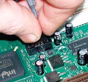
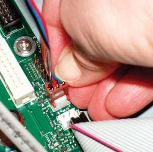
The final step in installing the hard drives is to connect the drive bay fan power cable. Locate that cable at the bottom rear of the drive bay (as shown back in Figure 4-29) and route it to one of the fan power headers at the front of the motherboard near the ATA interface connectors. The plug and socket are keyed with a slot and tab arrangement, as shown in Figure 4-38. Align the plug with the header pins, making sure the key slot is oriented correctly, and press the plug into the socket.
The Intel SC5250-E case provides two external 5.25” bays, each of which is covered by a snap-in plastic bezel and a metal RF shield. We decided to install the optical drive in the top bay. Before installing the drive, you have to remove the bezel and the RF shield for the selected drive bay. To remove the drive bay bezel, simply lay the main system bezel facedown on the table. Working from the rear, press the plastic tabs on the drive bay bezel to release the tension and snap it out. To remove the RF shield, place a finger in one of the large holes near the side of the shield and tug on it until is snaps out, as shown in Figure 4-39.
Before you install the optical drive, verify the jumper settings. We plan to use the optical drive as the secondary master, leaving the primary ATA channel unused. Our optical drive was jumpered as master by default, so we didn’t need to change the setting.
The Intel SC5250-E case uses something we haven’t seen for a long time. Its drive rails come in Left and Right versions that are not interchangeable, and they secure both to the drive and to the case. Shades of the 1986-era IBM PC-AT. We had to search for the drive rails. We finally found them in an oblong white cardboard box with several other minor components, including rubber feet for the case.
Choose one of each type of drive rail and install them as shown in Figure 4-40, using screws from the plastic bag labeled “B.” Align the rails as shown, with the bottom of the rail near the bottom of the drive and about 3/4” (19mm) of space between the front of the rail and the front of the drive. Getting the first part wrong means the drive won’t fit into the bay. Getting the second part wrong means the drive won’t seat flush with the main system bezel.
It’s easier to connect the ATA cable to the optical drive before you install the drive in the case. The Intel S875WP1 motherboard included an ATA cable, which we used to connect the optical drive. That cable is an 80-wire UltraDMA cable, which is really intended for use with a fast hard drive, but works fine with any ATA/ATAPI drive. A standard 40-wire ATA cable would have been good enough for the optical drive, but we used what we had.
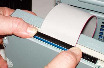
To connect the cable, locate pin 1 on the drive connector, which is usually nearest the power connector. The pin 1 side of the cable is indicated by a red stripe. Align the cable connector with the drive connector, making sure the red stripe is on the pin 1 side of the drive connector, and press the cable into place, as shown in Figure 4-41.
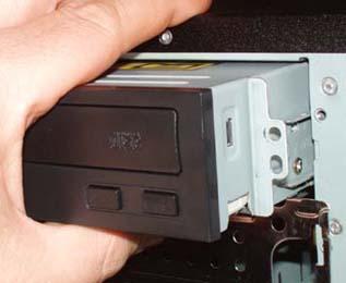
To mount the drive in the case, feed the loose end of the ATA cable through the drive bay from the front, align the drive rails with the corresponding slots in the case, and press the drive firmly into place, as shown in Figure 4-42. If you mounted the drive rails correctly, the drive should seat flush with the bezels that cover the vacant drive bays. It’s worth taking a moment to verify proper fit by temporarily replacing the main drive bezel. You don’t want to have to remove and reinstall the drive and all the cables if it turns out that the drive is seated too far in or too far out.
With the optical drive seated fully, secure it to the chassis by driving one screw on either side, as shown in Figure 4-43.
The next step is to connect power to the optical drive. For some reason, we often forget to do this, which means that when we’re ready to install the OS we often find ourselves shutting the system down, popping the cover, connecting power to the optical drive, and reassembling everything. It’s not just us, either. We’ve watched other people build systems, and they often forget to connect power to the optical drive.
Locate a drive power (“Molex”) connector coming from the power supply and route it to the back of the optical drive, making sure it is not tangled with or looped around other cables. Orient the cable connector properly—it’s keyed with diagonal bevels on one side—and press it into the power connector on the drive, as shown in Figure 4-44.
Note
It sometimes requires significant pressure to seat a Molex connector, so press until you feel it snap into place. It’s quite possible to think you’ve seated the connector properly only to find out later that it’s making partial or no contact. The Molex connector delivers both +5VDC and +12VDC. Many drives use 12V for the motor and 5V for the electronics. The usual symptom of a poor power connection is a dead optical drive, or one that spins up (because it is receiving 12V) but isn’t recognized by the system (because it isn’t receiving 5V).
Working from the rear of the drive, feed the ATA cable down into the case, placing the loose end near the front right edge of the motherboard. We want to connect the optical drive as the master device on the secondary ATA channel. The primary ATA and secondary ATA interfaces are located near the right front edge of the motherboard near the DIMM slots. The primary ATA interface is the black connector nearest the edge, and the secondary ATA interface is the white connector immediately adjacent. Locate pin 1 on the secondary ATA interface, align the ATA cable with its red stripe toward pin 1 on the interface, and press the connector into place, as shown in Figure 4-45.
The next step in assembling the system is to connect the two power connectors from the power supply to the motherboard. The Intel S875WP1 motherboard does not use a standard ATX12V power supply, although the connectors are similar. Instead, it uses an EPS12V power supply. The major differences between desktop-oriented ATX12V power supplies and server-oriented EPS12V power supplies are as follows:
- Main power connector
Standard ATX12V power supplies use a 20-pin main power connector. EPS12V power supplies use a 24-pin main power connector. The pinouts for the first 20 pins are identical. The EPS12V power supply adds pins 21 through 24. Pins 21, 22, and 23 use red wires and supply additional +5VDC. Pin 24 uses a black wire and is an additional COM (ground) pin.
- 12V CPU power connector
The ATX12V provides a 4-pin (2X2) supplemental power connector that provides additional +12VDC on two pins and ground on the other two pins. The EPS12V power supply provides an 8-pin (4X2) supplemental power connector that provides additional +12VDC on pins 5 through 8 and ground on pins 1 through 4.
The main power connector on the S875WP1 motherboard can accept either an ATX12V or an EPS12V main power connector. That doesn’t mean you can use an ATX12V power supply with this motherboard, though. The S875WP1 motherboard has an 8-pin socket for the EPS12V 12V CPU power connector. That socket is not compatible with the ATX12V 12V CPU power connector, and power must be connected to that socket for the motherboard to boot.
Note
You can install the S875WP1 motherboard in some standard ATX cases, but you must replace the ATX12V power supply with an EPS12V power supply, such as one of those available from Antec or PC Power & Cooling. Before you attempt this, make sure the EPS12V power supply fits the ATX case.
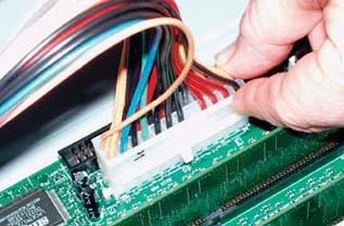
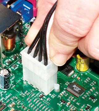
To connect power to the motherboard, locate the main EPS12V power connector, a 24-pin socket located near the right front edge of the motherboard. Locate the corresponding cable coming from the power supply. The connectors are keyed, so verify that the plug is aligned properly with the socket before you attempt to seat it.
Once everything is aligned, press down firmly until the plug seats completely in the socket, as shown in Figure 4-46. It may take significant pressure to seat the plug, and you should feel it snap into place. The locking tab on the side of the plug should snap into place over the corresponding nub on the socket. Make sure the connector seats fully. A partially seated power connector may cause subtle problems that are very difficult to troubleshoot.
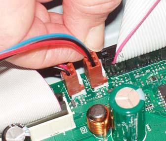
EPS12V motherboards require more +12VDC power than the 4-pin ATX12V connector supplies. For EPS12V, Intel substitutes the 8-pin 12V CPU power connector to route additional +12V current directly to the voltage regulator module that powers the processor(s). On most EPS12V motherboards, including the S875WP1, the 12V CPU power connector socket is located near the processor socket(s). The plug and socket are keyed. Orient the plug properly relative to the socket, and press the plug into place until the plastic tab locks, as shown in Figure 4-47.
Congratulations! You’re almost finished building the system. Only a few final steps remain to be done, and those won’t take long.
First, connect the supplemental case fan. The Intel SC5250-E has one rear-mounted 120mm supplemental fan. To enable it, connect its plug to a fan power connector on the motherboard, as shown in Figure 4-48.
Note
You might wonder why we connected the rear case fan to a fan power header at the front of the motherboard. It’s because we failed to see one of the fan power headers.
The S875WP1-E provides five 3-pin fan headers. Four of the five—CPU_FAN, SYSFAN1, SYSFAN2, and SYSFAN4—connect to the tachometer input of the Hardware Management ASIC, which allows the system to monitor and control the fans. The fifth fan header, SYSFAN3, provides power but not monitor or control features. SYSFAN3 is located near the rear of the case, well positioned for the rear case fan. But we wanted to be able to monitor the rear case fan, so we connected it to one of the managed fan headers at the front of the case, not noticing that the SYSFAN4 managed fan header was even closer to the fan than SYSFAN3.
It did seem a bit odd that Intel would not provide a rear managed fan header in an otherwise well-engineered motherboard, so we went off in search of another fan header. Sure enough, we found SYSFAN4 lurking between the CPU and the rear I/O panel. We’ll fix that when we tie off and dress the cables.
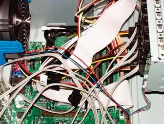
The final major step in assembling the system is to tie off and dress the cables. That simply means routing the cables away from the motherboard and other components and tying them off so they don’t flop around inside the case. Chances are, no one but you will ever see the inside of your system, but dressing the cables has several advantages other than making the system appear neater. First and foremost, it improves cooling by keeping the cables from impeding airflow. It can also improve system reliability. More than once, we’ve seen a system overheat and crash because a loose cable jammed the CPU fan or case fan. Second, it makes it much easier to work on the system later on. Figure 4-49 shows what the SOHO server looked like before we dressed the cables.
You can use anything handy to tie off and dress the cables. We’ve used commercial tie-wraps, wire twist ties (be careful not to short anything out with the exposed wire at the ends), the yellow plastic ties that come with garbage bags, rubber bands, packing tape, and so on. Figure 4-50 shows the result of five minutes spent tying off and tucking the cables.
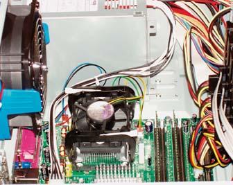
Note that the CPU cooling fan is unobstructed and that few cables intrude on the motherboard. The rear case fan and the power supply fan are both clear of obstructions, and there is a clear airway between the hard drive bay and the rear case fan. We tucked excess cable lengths into the nooks and crannies of the case to prevent them from flopping around.
The CPU fan cable and the 12V CPU power connector cable are wedged against the side of the HSF mounting bracket to keep them clear of the CPU fan. The unused cables from the power supply are tucked into a vacant external drive bay, as is the slack in the power supply cables that connect to the hard drive bay and the motherboard. Get your own server dressed this neatly, and you won’t have to worry about obstructed airflow causing overheating.
You probably have the system on its side, so now is a good time to attach the rubber feet to the bottom of the case. Once that’s done, return the case to its normal vertical orientation and remount the main system bezel. To do so, align the three plastic tabs on the right side of the bezel with the corresponding slots in the frame, and then swing the bezel closed until the two locking tabs on the left side of the bezel snap into place.
After you’ve completed these steps, double-check everything. Verify that all cables are connected properly, that all drives are secured, and that there’s nothing loose inside the case. It’s a good idea to pick up the system and tilt it gently from side to side to make sure there are no loose screws or other items that could cause a short. Use the following checklist:
| — No loose tools or screws (shake the case gently) |
| — Heatsink/fan unit properly mounted; CPU fan connected |
| — Memory modules fully seated and latched |
| — Front-panel switch and indicator cable connected properly |
| — Front-panel USB cable connected properly |
| — Hard drive data cables connected to drives and motherboard |
| — Hard drive power cables connected |
| — Hard drive bay fan power cable connected |
| — Optical drive data cable connected to drive and motherboard |
| — Optical drive power cable connected |
| — Optical drive audio cable(s) connected (if applicable) |
| — Floppy drive data and power cables connected (if applicable) |
| — All drives secured to drive bay or chassis |
| — Expansion cards fully seated and secured to the chassis (if applicable) |
| — Main EPS12V power cable and supplemental 12V power cable connected |
| — Front and rear case fans installed and connected |
| — All cables dressed and tucked |
Once you’re certain that everything is correct, it’s time for the smoke test. Leave the side panel off for now. Connect the power cable to the wall receptacle and then to the system unit. The green LED near the center of the motherboard should illuminate as soon as you connect power to the power supply. Press the main power button on the top front of the case to start the system. Verify that the power supply fan, CPU fan, and case fan are spinning. At that point, everything should be working properly.
Turn off the system, disconnect the power cord, and take these final steps to prepare the system for use:
- Set the BIOS Setup configuration jumper to Configure mode
The BIOS Setup configuration jumper block on the Intel S875WP1 motherboard is used to set the operation mode. This jumper is located on the left front of the motherboard, adjacent to the front-panel connector cable. By default, the jumper is in the 1-2 (Normal) position. Move the jumper block to the 2-3 (Configure) position.
- Configure BIOS settings
After you set the configuration jumper to Configure mode, connect the monitor, keyboard, and mouse, reconnect the power cord, and start the system. BIOS Setup runs automatically and puts the system in maintenance mode. This step allows the motherboard to detect and configure the processor. When the BIOS Setup screen appears, clear all BIOS data and reset the system clock. Verify all other BIOS settings and change them as necessary to suit your preferences. Save the changes and exit. The system automatically shuts down. Disconnect the power cord.
Note
For details about BIOS configuration, refer to Chapter 7 of the Intel Server Board S875WP1-E Technical Product Specification and the latest Specification Update. These PDF documents can be downloaded from the Intel web site. (We can’t give URLs because they change each time the documents are updated.)
- Set the BIOS Setup configuration jumper to Normal mode
With the power cord disconnected, move the BIOS Setup configuration jumper block from 2-3 (Configure mode) to 1-2 (Normal mode).
- Replace the side panel and reconnect power
With the jumper set for Normal operation, replace the side panel and reconnect the power cord. Your system is now completely assembled and ready for use.
Note
For most cases we’ve used, the side-panel latch alone is sufficient to secure the side panel, so we usually don’t bother to reinsert the shipping screws. The Intel SC5250-E case has two blue plastic locking tabs on the rear of the side panel, but they didn’t look sufficiently robust to secure the side panel reliably, so we reinserted both shipping screws.
- Configure the RAID
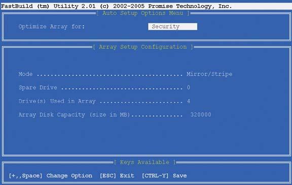
Power up the system and press Ctrl-F to enter the Promise FastBuild Utility. (You may have to press Ctrl-F “blind” as the system boots, because the monitor may not display an image before the boot process passes the point where it prompts you to enter RAID setup.) By default, the array is configured in Performance mode, which stripes all four drives in a RAID 0. Use the down-arrow key to go to the first field, and press the spacebar to change “Performance” to “Security.” The screen should now look similar to Figure 4-51. If you used hard drives with capacities other than 160 GB each, the array disk capacity figure will be different.
Press Ctrl-Y to save the array settings. The system prompts you to press “Y” to create the array and overwrite the Master Boot Record (MBR), or “N” to create the array without overwriting the MBR. Press “Y” to create the array and a new MBR. The system then prompts you to confirm that choice. Do so to create the array and then reboot the system.
- Configure boot device priority
With the array defined, restart the system and press F1 to invoke the BIOS Setup utility. Again, you may have to press F1 “blind” because the monitor may not display the Boot screen quickly enough for you to see the BIOS Setup prompt. Pressing F1 repeatedly while the system boots does no harm.
When the BIOS Setup screen appears, use the right arrow to select the Boot Menu. Choose the Boot Device Priority to specify the boot sequence. Select the optical drive as the first boot device and the array as the second boot device. (You cannot do this earlier because the array is not listed as a boot option until you have configured it.) After you have configured the boot sequence properly, press F10 to save your changes and exit BIOS Setup.
Get Building the Perfect PC now with the O’Reilly learning platform.
O’Reilly members experience books, live events, courses curated by job role, and more from O’Reilly and nearly 200 top publishers.

