The motherboard is the most complex component in a PC. All of the other components connect to and are controlled by the motherboard, so it’s important to be able to identify its major parts.
Figure 1-2 shows the major components present on a representative modern motherboard, in this case an Intel D865GBF for a Pentium 4 processor. The rest of this section includes photographs of each of these components to help you visually identify items. The details and layout vary from model to model, but all modern motherboards include these or similar components. Once you’re able to locate and identify the major components on one motherboard, you should be able to do the same on any other motherboard.
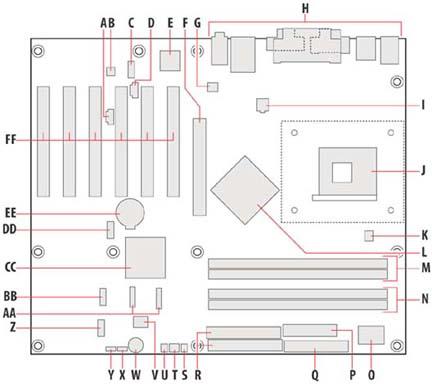
Most of these items are reasonably self-explanatory, but a few deserve comment:
- Intel D82865G GMCH (Item L)
The Intel D82865G GMCH is the Graphics and Memory Controller Hub, which in a non-Intel chipset would be called the northbridge. The GMCH provides the link between the processor and memory, and also includes the circuitry for the embedded video.
- 4 Mbit Firmware Hub (Item V)
The Intel Firmware Hub (FWH) stores the BIOS code and BIOS Setup configuration data in nonvolatile read/write memory. When you update the main system BIOS, the new BIOS code is written to the FWH.
- Intel 82801EB I/O Controller Hub (Item CC)
The Intel 82801EB I/O Controller Hub (ICH5) is what would be referred to as the southbridge in a non-Intel chipset. The ICH provides an interface between the GMCH, the BIOS, and major system communication peripherals, including the PCI bus, USB, and the ATA and S-ATA interfaces. It also provides the circuitry for the embedded audio.
Figure 1-3 shows the relationship between the GMCH, the ICH, and other major system components.

Figure 1-4 shows the left rear quadrant of the D865GBF motherboard. The six light-colored PCI bus add-in card connectors (Item FF)—also called simply "PCI slots”—dominate this image. The auxiliary line-in connector (A), which can be used to route analog audio from an optical drive, is visible between PCI slots 3 and 4, near the top. The audio codec (B), which processes audio data, is the small surface-mount chip just above the gap between PCI slots 3 and 4. The ATAPI CD-ROM connector (D) nestles between the top edges of PCI slots 4 and 5, with the front-panel audio connector (C), shown with two jumpers installed, immediately above it. The optional Ethernet PLC device (E), which provides the embedded Ethernet adapter, is the rectangular black chip just above PCI slot 6. The AGP connector (F) is the dark slot to the lower right of PCI slot 6. The rear chassis fan connector (G) is the small white plastic connector with three pins, visible above and to the right of the AGP slot. The battery (EE) is partially visible at the bottom center of the image, and the heatsink for the Intel 82865G GMCH (L) is partially visible at the lower right.
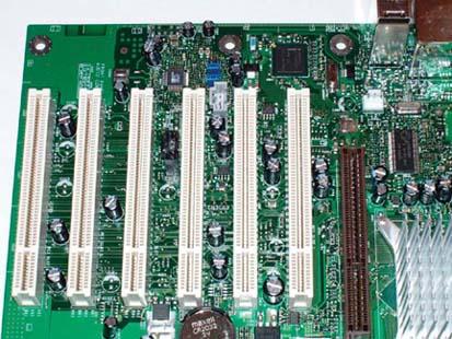
Figure 1-5 shows the right rear quadrant of the D865GBF motherboard. The back-panel connectors (H) are grouped on the upper right edge of the motherboard. The Pentium 4 processor socket (J) is the light-colored rectangle at the lower right of the image, with the processor fan connector (K) visible as a small, white, plastic three-pin connector at the extreme lower right of the image, to the right of the label. The ATX12V supplementary power connector (I) is the small connector block visible immediately to the left of the row of cylindrical capacitors above the processor socket. The Intel 82865G GMCH (L) is actually concealed by a heatsink, the large, finned object directly to the left of the processor socket.
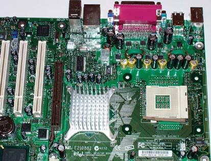
Figure 1-6 shows the right front quadrant of the D865GBF motherboard. The dark slots immediately below the heatsink and processor socket are the DIMM Channel A sockets (M) and the DIMM Channel B sockets (N). The I/O controller (O) is the rectangular black surface-mount chip at the extreme lower right. To its left are the translucent plastic 20-pin main ATX power connector (P) above, with the black 34-pin diskette drive connector (Q) below. The two connectors adjacent to the diskette drive connector and main ATX power connector are the parallel ATA IDE connectors (R). The lower, black connector is the primary ATA IDE connector. The white connector immediately above it is the secondary ATA IDE connector.
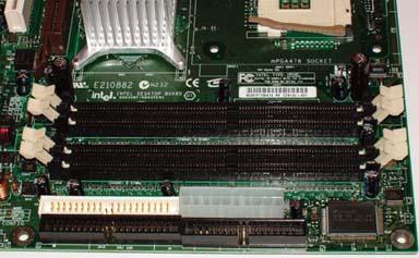
Figure 1-7 shows the left front quadrant of the D865GBF motherboard. Near the lower right corner of the image, adjacent to the mounting hole, is where the optional SCSI hard drive activity LED connector (S) would be if we had ordered that option. We didn’t, so the position for it is simply an empty solder pad. Immediately to the left of the nonexistent SCSI activity connector is the front chassis fan connector (T), the white plastic connector with three pins visible. To its left is the chassis intrusion connector (U), a two-pin black plastic connector.
The round object at the bottom center of the image is the speaker (W), and the 4 Mbit Firmware Hub (V) is the rectangular black surface-mount chip visible just above it. To the left of the speaker is the BIOS Setup configuration jumper block (X), shown jumpered in the 1-2 position. To the left of the jumper block is the auxiliary front-panel power LED connector (Y), a three-position jumper with pin 2 absent. The front-panel connector (Z) is the white plastic connector block with several pins, visible above and to the left.
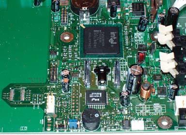
The Intel ICH5 82801EB I/O Controller Hub (CC) is the large, square black chip at the upper center of the image, with two Serial ATA connectors (AA) immediately beneath it. There are two front-panel USB connectors. One of those (BB) is directly to the left of the Serial ATA connectors, adjacent to two cylindrical capacitors. The second (DD) is at the upper left of the image, adjacent to the battery (EE).
Get Building the Perfect PC now with the O’Reilly learning platform.
O’Reilly members experience books, live events, courses curated by job role, and more from O’Reilly and nearly 200 top publishers.

