Appendix B. Using Schematic Diagrams and Data Sheets
A schematic diagram, also called a circuit diagram, is the standard way of describing the components and connections in an electronic circuit. It uses iconic symbols to represent components, with lines representing the connections between the components.
A circuit diagram represents the connections of a circuit, but it is not a drawing of the actual physical layout. Although you may initially find that drawings and photos of the physical wiring can be easier to understand than a schematic, in a complicated circuit it can be difficult to clearly see where each wire gets connected.
Circuit diagrams are like maps. They have conventions that help you to orient yourself once you become familiar with their style and symbols. For example, inputs are usually to the left, outputs to the right; 0V or ground connections are usually shown at the bottom of simple circuits, the power at the top.
Figure A-1 in Appendix A shows some of the most common components, and the symbols used for them in circuit diagrams. Figure B-1 is a schematic diagram from Recipe 8.6 that illustrates the symbols used in a typical diagram.
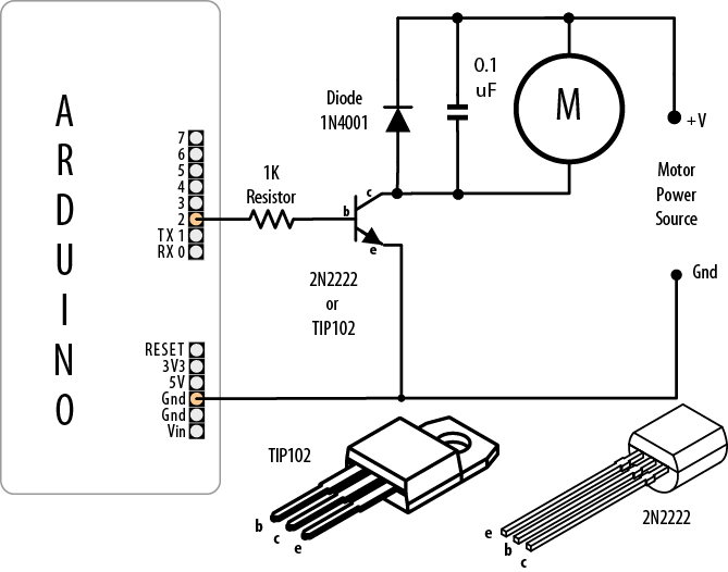
Components such as the resistor and capacitor used here are not polarized—they can be connected either way around. Transistors, diodes, and integrated circuits are polarized, so it is important that ...
Get Arduino Cookbook now with the O’Reilly learning platform.
O’Reilly members experience books, live events, courses curated by job role, and more from O’Reilly and nearly 200 top publishers.

